Pillar for a motor vehicle and method for manufacturing a pillar

a technology for motor vehicles and pillars, applied in the direction of superstructure subunits, furnace types, furnaces, etc., can solve the problems of only limited wall thickness reduction, unavoidable zones can be affected, etc., to achieve the effect of ensuring weldability, reducing carbon content, and increasing bending angl

Inactive Publication Date: 2018-02-01
BENTELER AUTOMOBILTECHNIK GMBH
View PDF0 Cites 10 Cited by
  • Summary
  • Abstract
  • Description
  • Claims
  • Application Information

AI Technical Summary

Benefits of technology

[0012]According to one exemplary embodiment, suitable steel alloys for the middle layer of the main element are boron steels with the main alloy elements of carbon and manganese, for example 22MnB5, 38MnB5.
[0013]In the scope of the invention, the tensile strength in the main element is at maximum 2200 MPa, wherein this limit arises in particular from the currently available and processible alloy composition of the hardenable steel alloys.
[0014]In particular, the pillar is a center pillar which, in addition to the main element and secondary element, also comprises a closing panel, by which a cavity is bounded, at least in cross section in the central longitudinal section. The closing panel is particularly advantageously connected to the main element by welding spots.
[0015]According to one exemplary embodiment, there is provision that the outer layer of the main element is composed of a ferritic stainless steel alloy, wherein the outer layer is connected to the middle layer in a planar and materially joined fashion. Two outer layers are preferably connected to the middle layer. In this context, the outer layers and the middle layer are already connected before the shaping in the form of a strip, for example by common hot rolling to form a sheet-metal material. By virtue of the reduced carbon content of the ferritic stainless steel alloy, the outer layer brings about a significantly increased bending angle of the sheet-metal material or of the main element in the form-hardened state and additionally outstanding resistance to corrosion, even to crevice corrosion and contact corrosion. Furthermore, with respect to usable ferritic stainless steel alloys reference is made hereby to the content of EN 10088-1 with chrome content values between 10.5 and 30% by weight depending on the type. In order to ensure the weldability, stabilizing additives are used of less than 0.5% by weight of titanium, niobium and / or zircon, as well as the carbon content which is limited to 0.16% by weight. The content by mass of carbon in the outer layer is preferably between 0.03 and 0.16% by weight, wherein the outer layer has in each case a thickness between 40 μm and 400 μm, in particular between 80 and 250 μm.
[0016]There can be provision that the central longitudinal section is formed with a U-shaped profile in cross section. As a result, on the one hand, a main element which runs continuously from the roof to the vehicle floor is provided, and on the other hand the cross section, with a U-shaped profile, of the central longitudinal section of the main element serves to make available a maximum flexural strength. The cross section in the central longitudinal section can also be formed with a hat-shaped profile, instead of a U-shaped profile.
[0017]The secondary element is advantageously connected to the main element in the central longitudinal section at an inner side of the main element to form a double-sheet layer. As a result, the central longitudinal section can be reinforced further, in particular in conjunction with a cross section with a U-shaped profile, without having to make the wall thickness of other sections of the main element into which fewer bending loads are introduced in the installed state unnecessarily thick or heavy.

Problems solved by technology

A disadvantage with the known component design is that a specific heating process has to be carried out before the form-hardening or alternatively after the form-hardening in order to ensure targeted deformation, and in addition, owing to the relatively soft predefined deformation region, the wall thickness can be reduced only to a limited degree, which holds potential for further lightweight design optimization.
These unavoidable zones can be zones affected by heat as a result of thermal joining methods such as spot welding or plug welding but also trimming edges or edges of holes caused by laser beams.

Method used


Image

  • Pillar for a motor vehicle and method for manufacturing a pillar
  • Pillar for a motor vehicle and method for manufacturing a pillar
  • Pillar for a motor vehicle and method for manufacturing a pillar

Examples


first embodiment

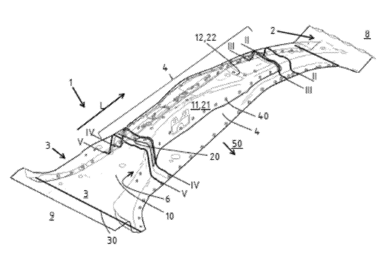
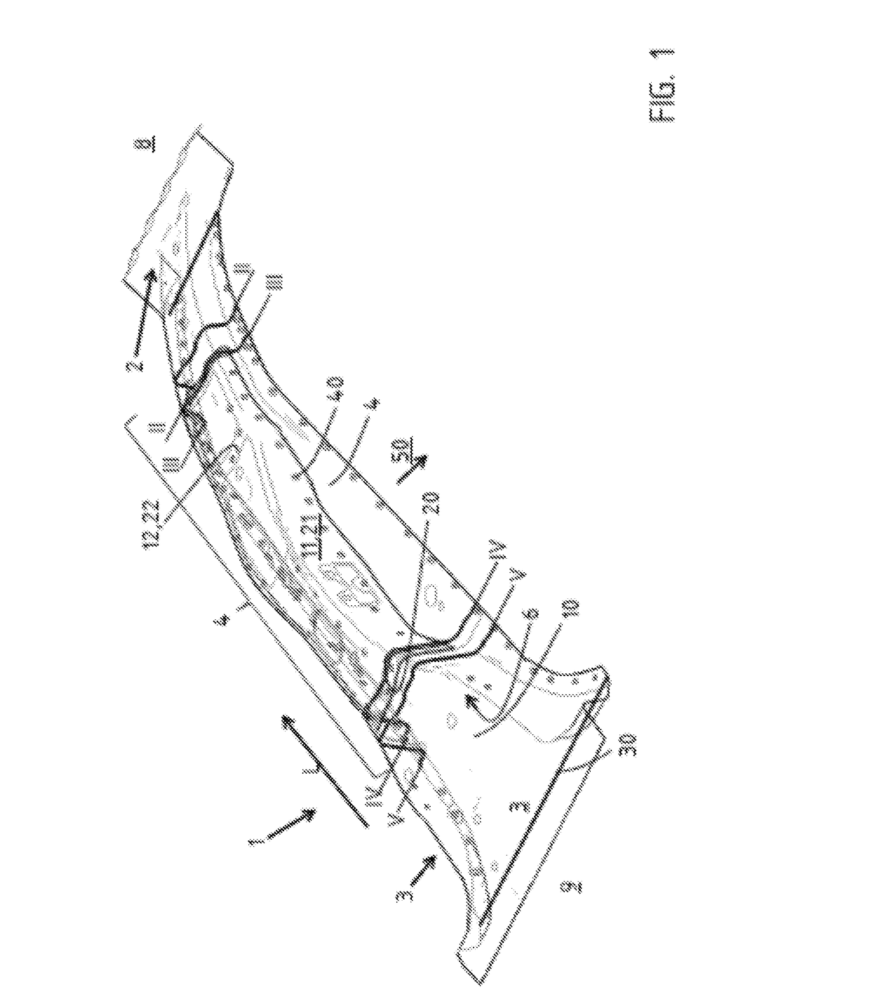
[0051]FIG. 1 shows a first embodiment variant of the pillar 1 according to the invention. In the installation position, the pillar 1 extends from a sill (not shown) of a vehicle bodywork to a roof frame (not illustrated). The pillar 1 has an upper coupling section 2 at the roof-side end 8 and a lower coupling section 3 at the sill-side end 9 shown at the bottom in the plane of the figure. A central longitudinal section 4, which is formed with a U-shaped or hat-shaped cross section, extends between the coupling sections 2, 3.

[0052]The pillar 1 comprises a main element 10, in particular composed of a sheet-metal material, and a secondary element 20, wherein the secondary element 20 is connected here essentially over the entire surface to the main element 10. The connection is preferably made by thermal joining, wherein welding spots 40 are illustrated here between two limbs 11 of the main element 10 and two limbs 21 of the secondary element 20. The limbs 11, 21 are each connected by a...

second embodiment

[0065]FIG. 10 shows a second embodiment variant of the pillar 1 according to the invention. The pillar 1 extends in the installation position from a sill of a vehicle bodywork to a roof frame. The pillar 1 has a main element 10 with an upper coupling section 2 arranged at the roof-side end 8, and a secondary element 20 which extends downward in the plane of the figure, in the direction of a sill-side end 9, and a lower coupling section 3′. A central longitudinal section 4 of the main element 10, which is formed with a U-shaped or hat-shaped cross section, extends between the coupling sections 2, 3′.

[0066]The pillar 1 comprises a main element 10, in particular composed of a sheet-metal material, and a secondary element 20, wherein the secondary element 20 is connected here essentially over the entire surface to the main element 10 in the central longitudinal section 4. The connection is preferably made by thermal joining, wherein welding spots 40 are illustrated here between two limb...


PUM

PropertyMeasurementUnit
tensile strengthaaaaaaaaaa
bending angleaaaaaaaaaa
tensile strengthaaaaaaaaaa

Abstract

A pillar for a motor vehicle bodywork is disclosed having a main element with an upper coupling section for attaching to a roof frame, and a secondary element composed of metallic alloy. The secondary element is connected in a planar fashion at least over certain sections of the main element, and the main element has a middle layer composed of a hardened steel alloy, and at least one outer layer which bounds the middle layer toward the outside.

Description

RELATED APPLICATIONS[0001]The present application claims the priority from German Application Number 10 2016 114 062.7, filed Jul. 29, 2016, the disclosure of which is hereby incorporated by reference herein in its entirety.BACKGROUND1. Field of the Invention[0002]The disclosure is related to a pillar for a motor vehicle, and mores specifically, to a center pillar for a passenger car.2. Description of the Related Art[0003]Vehicle pillars are part of the vehicle bodywork and connect the vehicle roof, in particular the roof frame, to the vehicle floor, usually in the form of a sill. Vehicle pillars are as a rule manufactured from sheet-metal material with a monocoque construction and serve, as a structural component of the vehicle bodywork, for protecting the vehicle occupants, but also make a substantial contribution to the overall stiffness of the motor vehicle. In particular the center pillar serves to provide side impact protection and prevents another party in an accident or an o...

Claims


Application Information

Patent Timeline
Patent Type & Authority Applications(United States)
IPC IPC(8): B62D25/04B21K29/00B21K7/12B62D29/00B21J5/12
CPCB62D25/04B62D29/007B62D65/00B21K7/12B21K29/00B21J5/12C21D1/18C21D9/0068B21D22/208B21D53/88C21D1/673
Inventor VON WATZDORF, HENNINGFROST, GEORGSCHROETER, MARTIN
Owner BENTELER AUTOMOBILTECHNIK GMBH
Why Eureka
Try Eureka