System and method for three-dimensional micro particle tracking

a three-dimensional tracking and micro particle technology, applied in the field of three-dimensional tracking micro particle motion, can solve the problems of inaccurate measurement under high magnification image, inconvenient defocusing method and image aberration method for broad-range measurement, and track two-dimensional motion of particle, so as to reduce the cost of the system, reduce the error of measurement, and improve the information-noise ratio of the image

Inactive Publication Date: 2018-02-15
NATIONAL TAIWAN OCEAN UNIVERSITY
View PDF2 Cites 4 Cited by
  • Summary
  • Abstract
  • Description
  • Claims
  • Application Information

AI Technical Summary

Benefits of technology

[0009]The present invention provides a system and method for three-dimensionally tracking a particle motion where the measurement errors are reduced and information-noise ratio of the image is greatly improved simultaneously. In addition, the present invention can capture the interference image of particles within the fluid sample by utilizing a consumer electronic camera such that not only the cost of the system is greatly reduced, but also the signal noise is eliminated so as to increase the S / R ratio. In addition to the consumer electronic camera, alternatively, high-speed camera can also be another embodiment for capturing interference image.

Problems solved by technology

Unlike the conventional measuring method and system, the PIV technique can accurately measure high resolution velocity fields without using intrusive manner to interfere the fluid motion thereby causing an inaccurate result.
Although conventional PIV technique, such as micro-PIV, can be utilized to track the particle motion, it can only track two-dimensionally motion of the particle.
The defocusing method and image aberration method are not suitable for broad range measurement because these methods have low signal-to-noise (S / R) ratio caused by insufficient luminous flux.
Regarding the method proposed by Rossi, it can have accurate measurement under lower magnification image whereas measurement under high magnification image is inaccurate.
Although Snoeyink can accurately measure the tracking information along depth direction (vertical direction), the distance for forming an image after the light passing the axicon is 20 cm or above such that it will be complicated to adjust the optical path and optical system configuration.

Method used


Image

  • System and method for three-dimensional micro particle tracking
  • System and method for three-dimensional micro particle tracking
  • System and method for three-dimensional micro particle tracking

Examples


Embodiment Construction

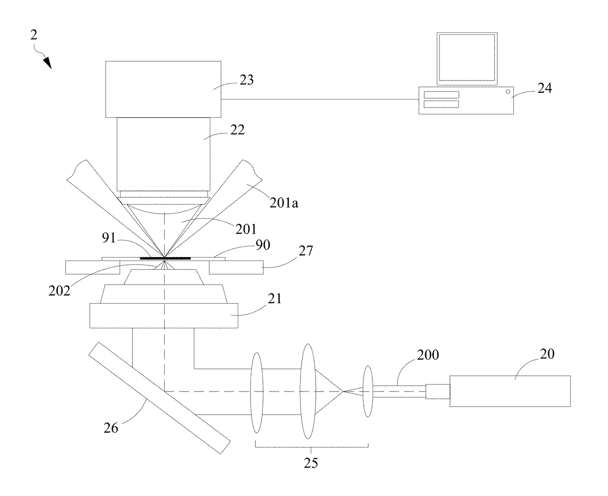
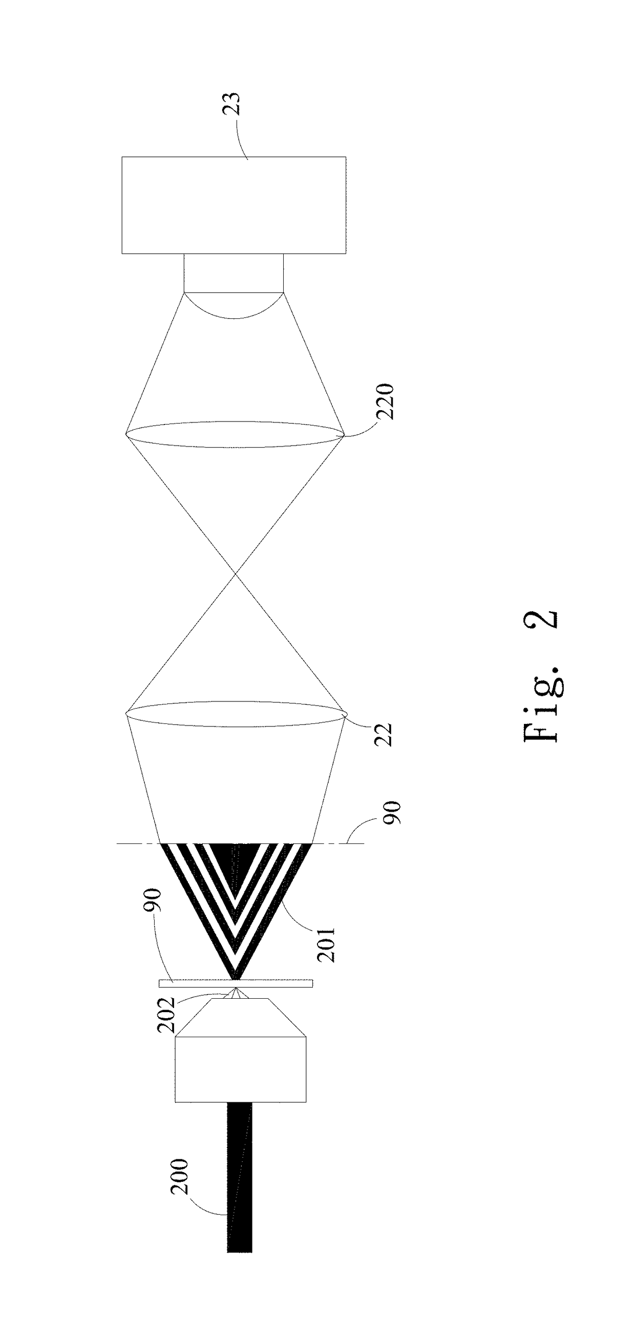
[0024]The invention disclosed herein is directed to a system and method for tracking particle motion along vertical direction, i.e. direction parallel to the optical axis of objective. In the following description, numerous details corresponding to the aforesaid drawings are set forth in order to provide a thorough understanding of the present invention so that the present invention can be appreciated by one skilled in the art, wherein like numerals refer to the same or the like parts throughout.

[0025]Although the terms first, second, etc. may be used herein to describe various elements, components, modules, and / or zones, these elements, components, modules, and / or zones should not be limited by these terms. Various embodiments will now be described in conjunction with a number of schematic illustrations. The embodiments set forth a system and method for tracking particle motion along vertical direction than conventional approaches. Various embodiments of the application may be embo...


PUM

PropertyMeasurementUnit
distanceaaaaaaaaaa
particle sizeaaaaaaaaaa
sizeaaaaaaaaaa

Abstract

The present invention provides system and method for three-dimensionally tracking micro particle motion wherein a dark-field condenser is configured to receive light field emitted from a light source and project the light field on a fluid sample having at least one particle thereby generating a scattered light field associated with the at least one particle, an objective lens is configured to receive the scattered light field, an image capturing unit coupled to the objective lens receives the scattered light field thereby generating at least one image of the fluid sample, and a controller is configured to couple to the image capturing unit for analyzing interference ring pattern corresponding to a specific particle in the at least one image and determining a tracking information associated with the specific particle along three-dimensional direction according to the size and center of the interference ring pattern.

Description

BACKGROUND OF INVENTION1. Field of the Invention[0001]The present invention relates to a system and method for tracking particle and, more particularly, to a system and method for three-dimensionally tracking micro particle motion within a fluid.2. Description of the Prior Art[0002]Particle image velocimetry (PIV) is a technique for measuring the velocity of the particle within a fluid. Unlike the conventional measuring method and system, the PIV technique can accurately measure high resolution velocity fields without using intrusive manner to interfere the fluid motion thereby causing an inaccurate result. Accordingly, the PIV technique can be applied in microfluidic devices utilized for performing tests of fluidic samples, such as fluids in microfluidic biochip, for example.[0003]In order to accurately monitor the velocity field of particle motion in the microfluidic devices, there has a need of three-dimensionally tracking particle motion within the fluid sample in the microfluid...

Claims


Application Information

Patent Timeline
Patent Type & Authority Applications(United States)
IPC IPC(8): G01N21/64G01N15/14
CPCG01N21/6456G01N15/1459G01N15/1434G01N2015/1075G01N2201/06113G01N2015/1465G01N2021/6421G01N2021/6478G01N2201/062G01N2015/1454G01N15/1468
Inventor SHEEN, JYH-JONGYEH, TZU-CHINGHUANG, YIN-HSUANCHIEN, HUNG-HSIANG
Owner NATIONAL TAIWAN OCEAN UNIVERSITY
Why Eureka
Try Eureka