Anti-Fogging and Anti-Fouling Laminate and Method for Producing Same, Article and Method for Producing Same, and Anti-Fouling Method
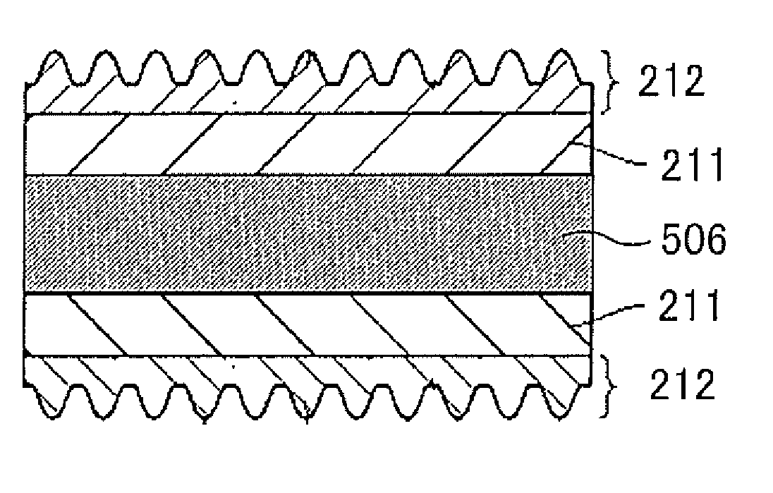
a technology of anti-fouling and anti-fouling, which is applied in the direction of synthetic resin layered products, vehicle components, domestic applications, etc., can solve the problems of low manufacture efficiency, reduced visibility and good appearance of products, and proposed techniques, and achieve excellent anti-fogging and anti-fouling properties, and also manufacture efficiency.
- Summary
- Abstract
- Description
- Claims
- Application Information
AI Technical Summary
Benefits of technology
Problems solved by technology
Method used
Image
Examples
first embodiment
[0217]The first embodiment is directed to an anti-fogging and anti-fouling layer forming step performed by using a transfer matrix having micro convex portions or micro concave portions which are formed by etching a surface of the transfer matrix with a photoresist having a predetermined pattern shape used as a protective film.
[0218]First, a transfer matrix and a method for manufacturing the transfer matrix will be described.
[Structure of Transfer Matrix]
[0219]FIG. 3A is a perspective view showing a structure of a roll matrix serving as a transfer matrix. FIG. 3B is an enlarged plan view of a part of the roll matrix shown in FIG. 3A. FIG. 3C is a cross sectional view taken along the line of track T in FIG. 3B. A roll matrix 231 is a transfer matrix for use in preparing an anti-fogging and anti-fouling laminate having the aforementioned constitution, and more specifically is a matrix for molding a plurality of convex portions or concave portions in the surface of the anti-fogging and...
second embodiment
[0238]The second embodiment is directed to the anti-fogging and anti-fouling layer forming step performed by using a transfer matrix having micro convex portions or micro concave portions which are formed by laser processing of the transfer matrix by irradiating the surface of the transfer matrix with the laser.
[0239]First, a transfer matrix and a method for manufacturing the transfer matrix will be described.
[Structure of Transfer Matrix]
[0240]FIG. 7A is a plan view showing a structure of a plate-form matrix. FIG. 7B is a cross sectional view taken long the line a-a, shown in FIG. 7A. FIG. 7C is an enlarged cross sectional view of a part of the section shown in FIG. 7B. A plate-form matrix 331 is a matrix for use in preparing an anti-fogging and anti-fouling laminate having the aforementioned constitution, more specifically, a matrix for molding a plurality of convex portions or concave portions in the surface of the anti-fogging and anti-fouling layer. The plate-form matrix 331 ha...
example 1
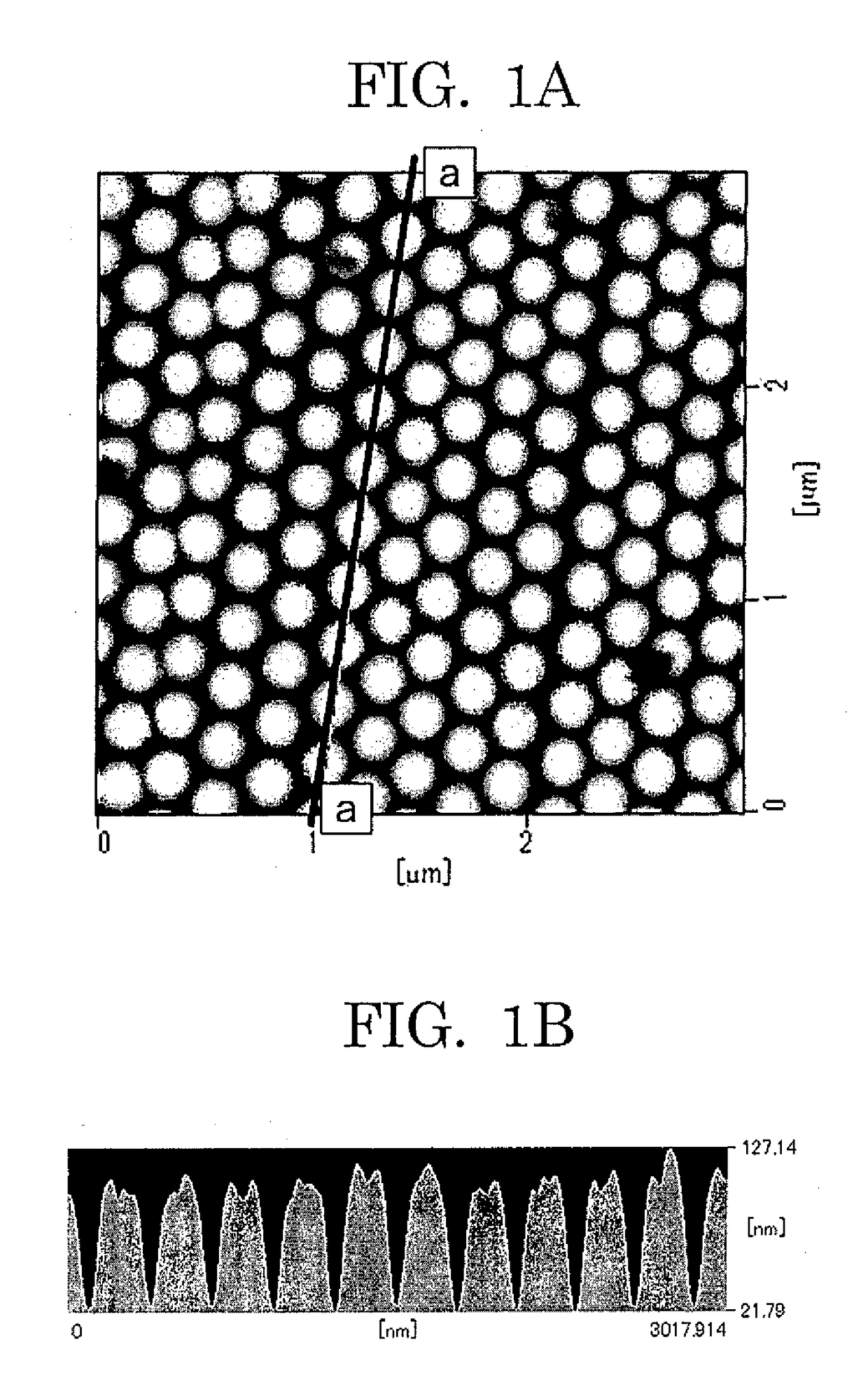
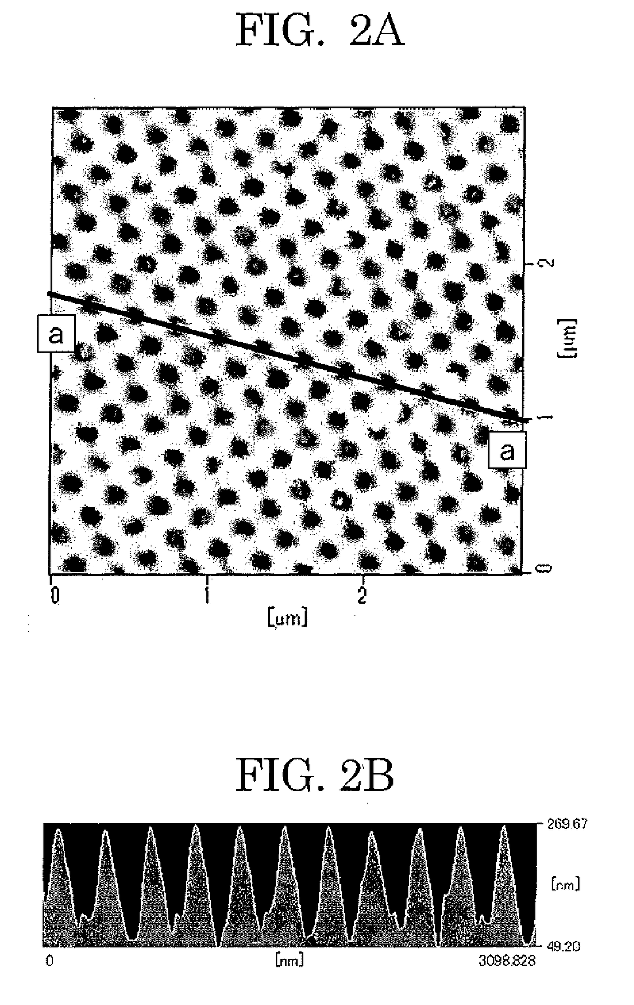
[0357]Firstly, a glass roll matrix having an outer diameter of 126 mm was prepared, and a resist layer was formed on the surface of the glass roll matrix in the following manner. Namely, a photoresist was diluted 1 / 10 by mass ratio with a thinner, and the diluted resist was applied to the cylindrical surface of the glass roll matrix in an average thickness of about 70 nm by a dipping method to form a resist layer. Next, the glass roll matrix was conveyed to an exposure apparatus for a roll matrix shown in FIG. 4, the resist layer was exposed, and thereby latent images lying in a spiral manner and forming a hexagonal lattice pattern between adjacent three rows of tracks was patterned on the resist layer. Specifically, an exposure pattern having a hexagonal lattice shape was formed by applying a 0.50 mW / m laser beam to a region where the exposure pattern having a hexagonal lattice shape to be formed.
[0358]Next, development processing was applied to the resist layer on the glass roll m...
PUM
| Property | Measurement | Unit |
|---|---|---|
| Pressure | aaaaa | aaaaa |
| Angle | aaaaa | aaaaa |
| Elongation | aaaaa | aaaaa |
Abstract
Description
Claims
Application Information
 - R&D
- Intellectual Property
- Life Sciences
- Materials
- Tech Scout
- Unparalleled Data Quality
- Higher Quality Content
- 60% Fewer Hallucinations
Browse by: Latest US Patents, China's latest patents, Technical Efficacy Thesaurus, Application Domain, Technology Topic, Popular Technical Reports.
© 2025 PatSnap. All rights reserved.Legal|Privacy policy|Modern Slavery Act Transparency Statement|Sitemap|About US| Contact US: help@patsnap.com


