Eureka AIR delivers breakthrough ideas for toughest innovation challenges, trusted by R&D personnel around the world.

Resonant high current density transformer with improved structure

Inactive Publication Date: 2018-03-01
YUJING TECH CO LTD
View PDF0 Cites 4 Cited by
  • Summary
  • Abstract
  • Description
  • Claims
  • Application Information

AI Technical Summary

Benefits of technology

The present invention is about a new type of transformer that can handle high amounts of electricity. It has a special design that allows for large amounts of copper to pass through, which is useful for applications where a lot of power needs to be converted. The transformer has multiple cores at the secondary side, which can be adjusted based on the power needs. This makes it easier to produce and assemble the transformer. Overall, the invention aims to create a better, more efficient transformer for high current density applications.

Problems solved by technology

Thus, this hinders the reduction in the size of the transformer.
The sum of the widths of the two metal plates and the width of the spacer equals the width of the primary winding on the first bobbin, and the spacer is not magnetically permeable, thus creating an air gap between the two metal plates, which leads to air gap losses.
3. The two metal plates and the second side posts of the cores in the above patent application are arranged perpendicular to each other, thus generating unnecessary magnetic shielding between the metal plates and the second side posts, increasing copper losses.

Method used


Image

  • Resonant high current density transformer with improved structure
  • Resonant high current density transformer with improved structure
  • Resonant high current density transformer with improved structure

Examples


Embodiment Construction

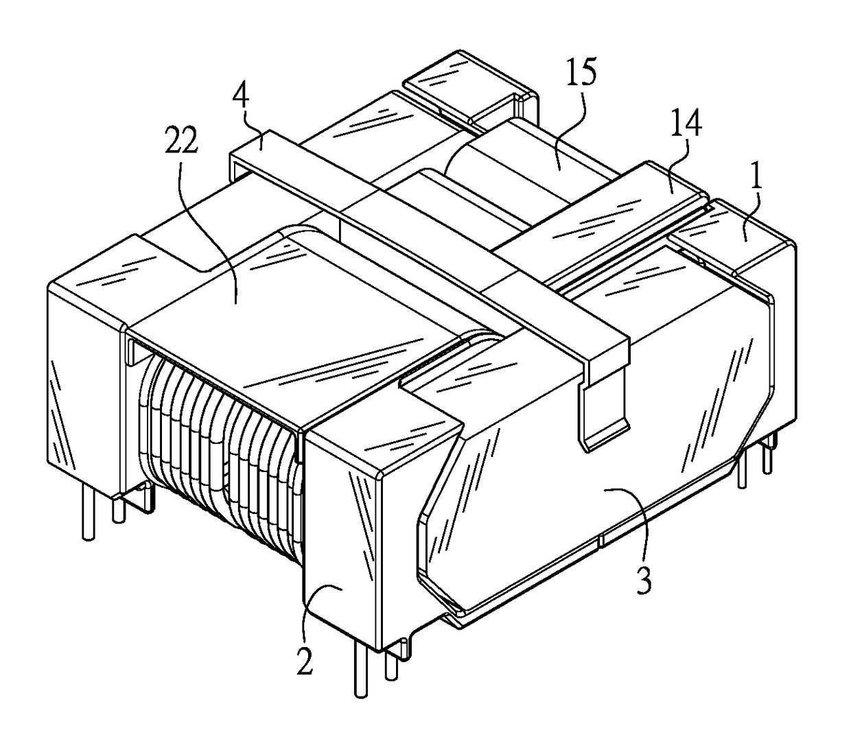
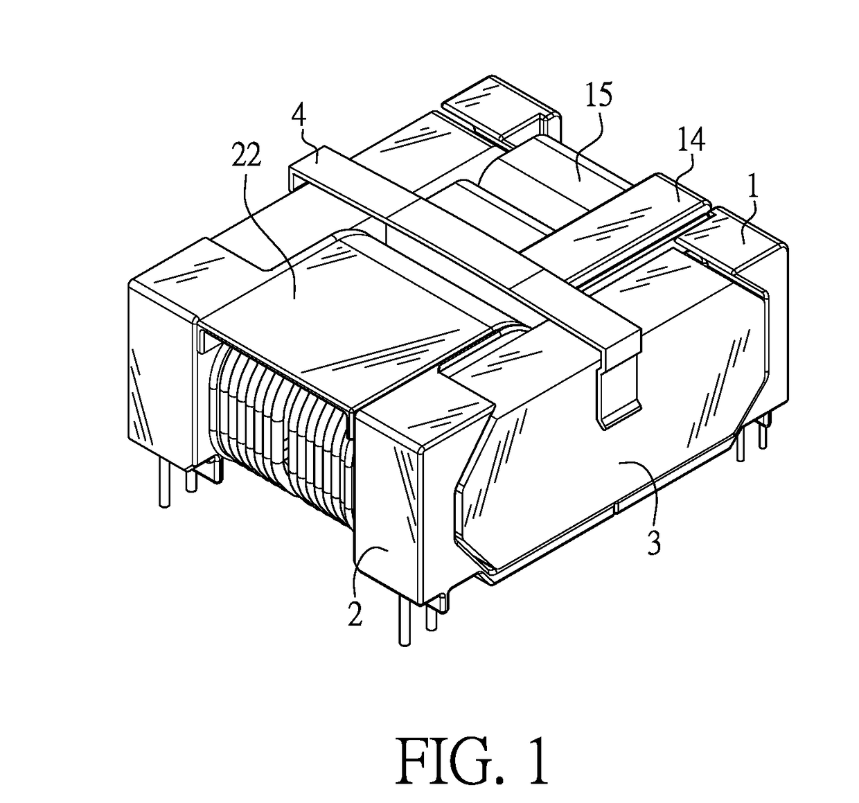
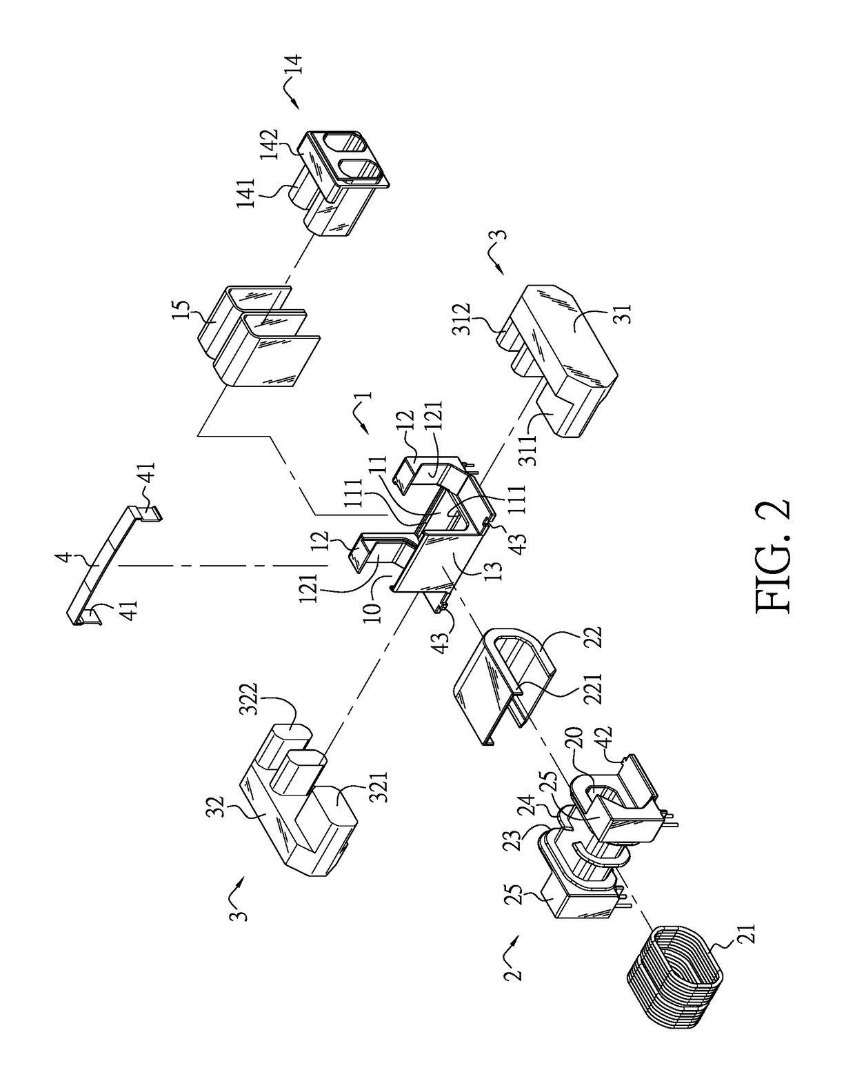
[0032]Referring to FIGS. 1 to 5, it can be understood that the structure of the present invention mainly includes the following.

[0033]A secondary insulating bobbin 1 with a base 11 is provided. The base 11 is provided with a plurality of through holes 111. A post 12 is provided extending from either end of one side of the base 11. A raised plate 13 extends from a location opposite to the middle of the two posts 12 on the other side of the base 11. The two posts 12 and the raised plate 13 together form a receiving space 10 for receiving an insulating sheath 14 with a plurality of sleeves 141. A securing plate 142 is extended from the top of the sleeves 141. A secondary winding 15 is provided on each of the sleeves 141. The secondary windings 15 are covered by the securing plate 142. An engaging face 121 is provided on a side of each of the posts 12 opposite the raised plate 13. It should be noted that, in order to allow large current to pass through while reducing copper losses, the ...


PUM


Abstract

A resonant high current density transformer with an improved structure includes a secondary insulating bobbin, a primary insulating bobbin and a core assembly. The secondary insulating bobbin includes a base. Two posts extend from a first side of the base, and a raised plate extends from a second side of the base, the second side is opposite to the first side. The two posts and the raised plate form a receiving space for receiving an insulating sheath having a plurality of sleeves. A secondary winding is provided on each of the sleeve. The primary insulating bobbin having a tunnel is provided at one side of the secondary insulating bobbin. The surface of the primary insulating bobbin is provided with a primary winding and covered by an insulating cover. A core assembly includes a first core and a second core. A first primary core column and a second primary core column opposite to each other extend from a side of the first and second cores, respectively, and a plurality of first secondary core columns and a plurality of second secondary core columns extend from another side of the first and second cores, respectively. The first primary core column and the second primary core column are inserted into the tunnel of the primary insulating bobbin, while each of the first secondary core columns and each of the second secondary core columns are inserted into a corresponding one of the sleeves. As a result, the secondary windings are capable of withstanding large current. Their overall length covers the air gap of the core assembly, thus achieving magnetic shielding. Meanwhile, production and assembly processes are simplified.

Description

BACKGROUND OF THE INVENTION1. Field of the Invention[0001]The invention relates to transformers, and more particularly, to a resonant high current density transformer with an improved structure that allows high current to pass through while increasing magnetic shielding at the secondary side, at the same time allows simplified production and assembly processes.2. Description of the Prior Art[0002]In power supply systems for electronic products such as LCD TVs, a main type of transformers used are transformers with leakage inductance property (such as LLC transformers) in order to reduce switching losses and noise.[0003]In TW Patent Publication No. 201619991 titled “Resonant High Current Density Transformer”, the transformer mainly includes: two cores, each including first and second side posts extending in the same direction from two sides thereof, wherein the two cores abut against each other with the two first side posts facing each other and the two second side posts facing each ...

Claims


Application Information

Patent Timeline
IPC IPC(8): H01F27/28H01F27/32H01F27/26H01F27/33H01F27/34
CPCH01F27/2847H01F27/325H01F27/34H01F27/289H01F27/33H01F27/26H01F27/266H01F27/306H01F27/36H01F27/263H01F27/2866H01F27/324H01F27/38
Inventor YANG, SEN-TAI
Owner YUJING TECH CO LTD
Why Eureka
Eureka Blog
Learn More