Hierarchical cascading in two-dimensional finite element method simulation of acoustic wave filter devices

a filter device and finite element technology, applied in the field of microwave filters, can solve the problems of filter steepness or selectivity, affecting the size and cost of a given resonator, and difficulty in describing open boundary conditions,

Active Publication Date: 2018-03-01
MURATA MFG CO LTD
View PDF7 Cites 17 Cited by
  • Summary
  • Abstract
  • Description
  • Claims
  • Application Information

AI Technical Summary

Benefits of technology

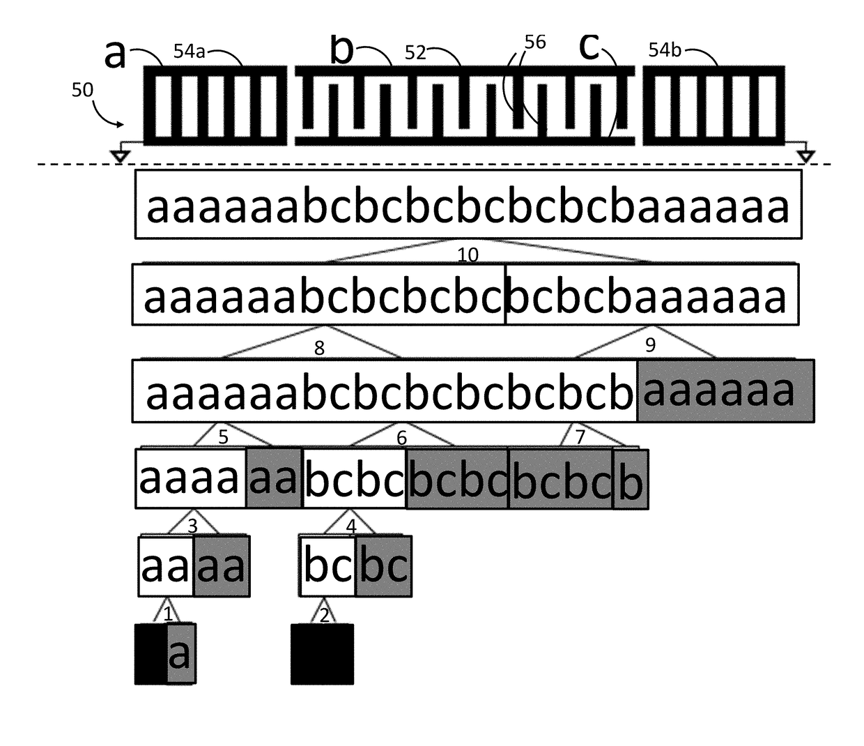
[0020]If FEM is used, combining the original unit blocks may comprises identifying a first set of adjacent original unit blocks and cascading the first set of adjacent original unit blocks into a first cascaded unit block by combining the B-matrices of the respective adjacent original unit blocks of the first set into a first C-matrix having left-side boundary DOFs corresponding to the left-side boundary DOFs of a left one of the adjacent original unit blocks, right-side boundary DOFs corresponding to a right one of the adjacent original unit blocks, and internal DOFs corresponding to at least one shared edge between the adjacent original unit blocks; and reducing the first C-matrix by removing the internal DOFs from the first C-matrix to a first new cascaded B-matrix of a first cascaded unit block comprising only left-side boundary DOFs and right-side boundary DOFs.
[0021]Then, the original unit blocks can be further combined by identifying a second set of adjacent original unit blocks, and cascading the second set of adjacent original unit blocks into a second cascaded unit block by combining the B-matrices of the respective adjacent original unit blocks of the second set into a second C-matrix having left-side boundary DOFs corresponding to the left-side boundary DOFs of a left one of the adjacent original unit blocks, right-side boundary DOFs corresponding to a right one of the adjacent original unit blocks, and internal DOFs corresponding to at least one shared edge between the adjacent original unit blocks; and reducing the second C-matrix by removing the internal DOFs from the second C-matrix to a second new cascaded B-matrix of a second cascaded unit block comprising only left-side boundary DOFs and right-side boundary DOFs.
[0022]Then, the original unit blocks can be further combined by identifying the first and second cascaded unit blocks as being a set of adjacent cascaded unit blocks, and further cascading the set of adjacent cascaded unit blocks into a third cascaded unit block by combining the B-matrices of the respective adjacent cascaded unit blocks of the set of cascaded unit blocks into a third C-matrix having left-side boundary DOFs corresponding to the left-side boundary DOFs of a left one of the adjacent cascaded unit blocks, right-side boundary DOFs corresponding to a right one of the adjacent cascaded unit blocks, and internal DOFs corresponding to at least one shared edge between the adjacent cascaded unit blocks; and reducing the third C-matrix by removing the internal DOFs from the third C-matrix to a third new cascaded B-matrix of a third cascaded unit block comprising only left-side boundary DOFs and right-side boundary DOFs. This process can be repeated unit a single block subsuming all of the unit blocks is created.

Problems solved by technology

In particular, such electrical filters are used to select desired electrical signal frequencies from an input signal by passing the desired signal frequencies, while blocking or attenuating other undesirable electrical signal frequencies.
This requirement for low resistance tends to drive the size and cost of the resonators for a given technology.
In most filter technologies, achieving a low insertion loss requires a corresponding compromise in filter steepness or selectivity.
Compared to Finite Element Method / Boundary Element Method (FEM / BEM) hybrid methods (see M. Solal, T. Abboud, S. Ballandras, S. Chamaly, V. Laude, R. Lardat, T. Pastereaud, J. Ribbe, W. Steichen, and P. Ventura, “FEM / BEM analysis for SAW structures,” Second International Symposium on Acoustic Waves Devices for Future Mobile Communication Systems, Chiba University, 2004), which does not easily address the complex structures of SAW devices, the advantage of FEM is its remarkable generality.
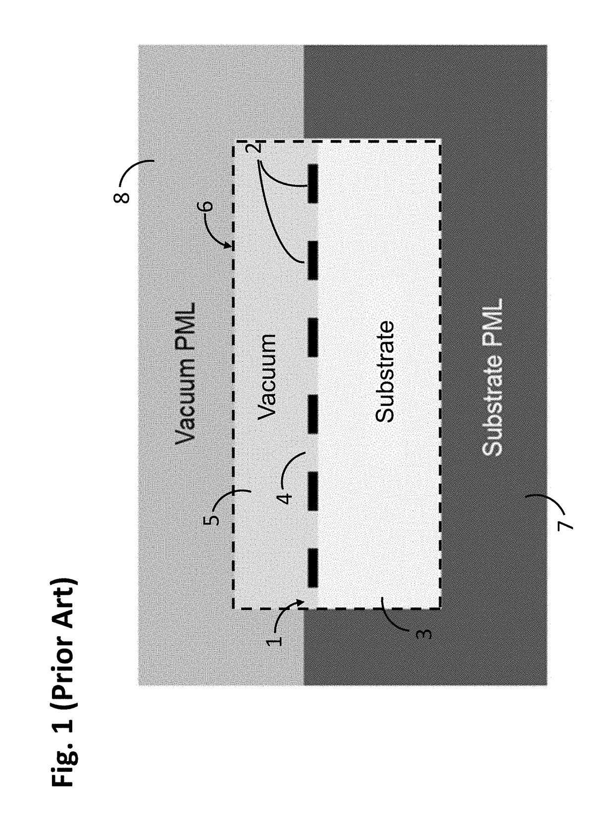
Traditionally, there have been two main problems in applying FEM to SAW structures: (1) the difficulty of describing open boundary conditions; and (2) the large number of degrees-of-freedom required to obtain high accuracy.
These problems manifest as large memory consumption and slow computation times.
This approach is unstable in some substrates with unsuitable anisotropy (see E. Becache, S. Fauqueux, and P. Joly, Stability of perfectly matched layers, group velocities and anisotropic waves, J. Comput. Phys., 188, pp.
Although the use of PMLs addresses the open boundary condition problem, the second problem of addressing the large number of degrees-of-freedom remains.

Method used


Image

  • Hierarchical cascading in two-dimensional finite element method simulation of acoustic wave filter devices
  • Hierarchical cascading in two-dimensional finite element method simulation of acoustic wave filter devices
  • Hierarchical cascading in two-dimensional finite element method simulation of acoustic wave filter devices

Examples


Embodiment Construction

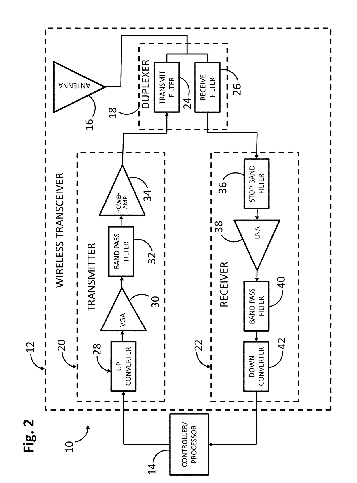
[0044]The present disclosure describes a technique for designing acoustic wave (AW) microwave filters (such as surface acoustic wave (SAW), bulk acoustic wave (BAW), film bulk acoustic resonator (FBAR), microelectromechanical system (MEMS) filters)). This technique can be applied to AW microwave filters in the 300 MHz to 300 GHz frequency range, particularly in the 300 MHz to 10.0 GHz frequency range, and even more particularly in the 400-3500 MHz frequency range. Such AW microwave filters may be either fixed frequency and / or tunable filters (tunable in frequency and / or bandwidth and / or input impedance and / or output impedance), and may be used for single-band or multiple-band bandpass and / or bandstop filtering. Such AW microwave filters are advantageous in applications that have demanding electrical and / or environmental performance requirements and / or severe cost / size constraints, such as those found in the radio frequency (RF) front ends of mobile communications devices, including ...


PUM


Abstract

A method of analyzing a microwave acoustic wave (AW) structure comprises defining a physical model of the AW structure, partitioning the physical model into a plurality of unit blocks, identifying at least one core block within the plurality of original unit blocks, computing characteristics of each of the at least one core block, deriving characteristics for each of the original unit blocks from the computed characteristics of the core block(s), combining the original unit blocks into a single block having computed characteristics derived from the characteristics of the unit blocks, such that the single block subsumes the plurality of original unit blocks, and deriving at least one electrical response of the physical model at least partially from the computed characteristics of the single block.

Description

CROSS-REFERENCE TO RELATED APPLICATION(S)[0001]This application claims priority from U.S. Provisional Patent Application Ser. No. 62 / 380,931 entitled “HIERARCHICAL CASCADING IN TWO-DIMENSIONAL FINITE ELEMENT METHOD SIMULATION OF ACOUSTIC WAVE FILTER DEVICES,” filed Aug. 29, 2016 under attorney docket number RES-022. The content of the aforementioned patent application is hereby expressly incorporated by reference in its entirety.FIELD OF THE INVENTION[0002]The present inventions generally relate to microwave filters, and more particularly, to a design process for acoustic microwave filters.BACKGROUND OF THE INVENTION[0003]Electrical filters have long been used in the processing of electrical signals. In particular, such electrical filters are used to select desired electrical signal frequencies from an input signal by passing the desired signal frequencies, while blocking or attenuating other undesirable electrical signal frequencies. Filters may be classified in some general catego...

Claims


Application Information

Patent Timeline
Patent Type & Authority Applications(United States)
IPC IPC(8): H03H3/08H03H9/64G06F17/50
CPCH03H3/08H03H9/64G06F2217/12G06F2217/16G06F17/5018G06F30/23G06F2119/18G06F2111/10
Inventor KOSKELA, JULIUSPLESSKI, VIKTOR
Owner MURATA MFG CO LTD
Why Eureka
Try Eureka