
Submerged combustion melters, wall structures or panels of same, and methods of using same

a technology of submerged combustion and burners, which is applied in the direction of combustion types, lighting and heating apparatuses, manufacturing tools, etc., can solve the problems of rapid melting of feedstock or parts, high turbulence and foaming, and it is not economically feasible to fabricate the entire burner using these materials. , to achieve the effect of reducing thermal fatigue and reducing flame impingemen

Active Publication Date: 2018-03-08
JOHNS MANVILLE CORP
View PDF9 Cites 12 Cited by
  • Summary
  • Abstract
  • Description
  • Claims
  • Application Information

AI Technical Summary

Benefits of technology

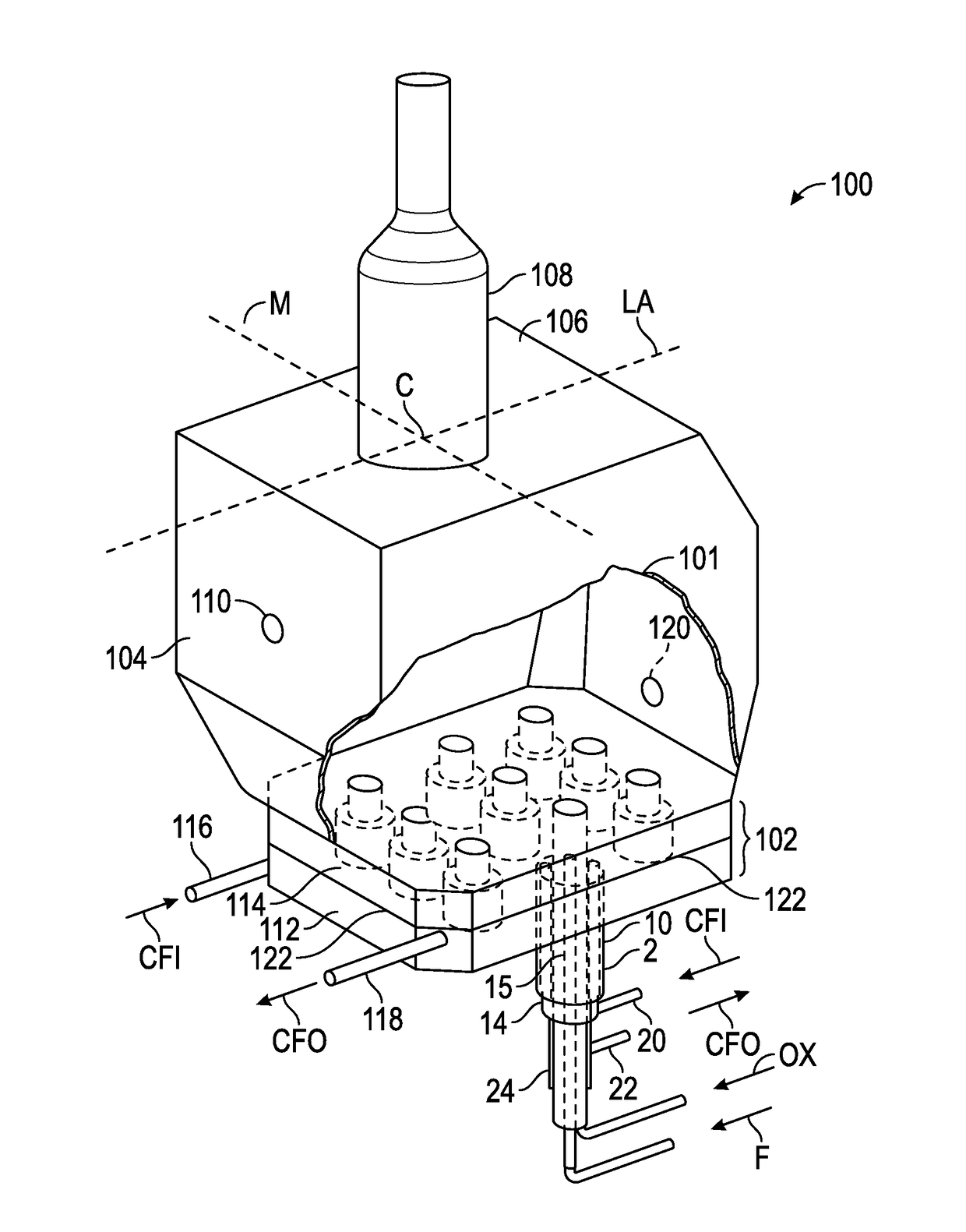
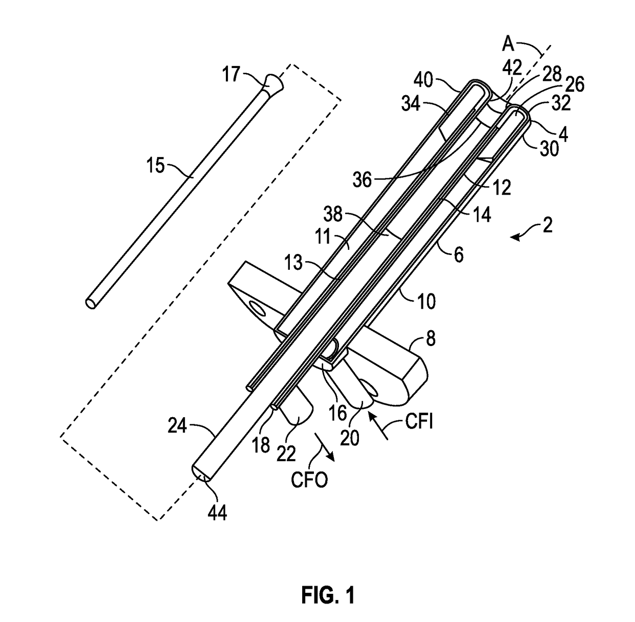
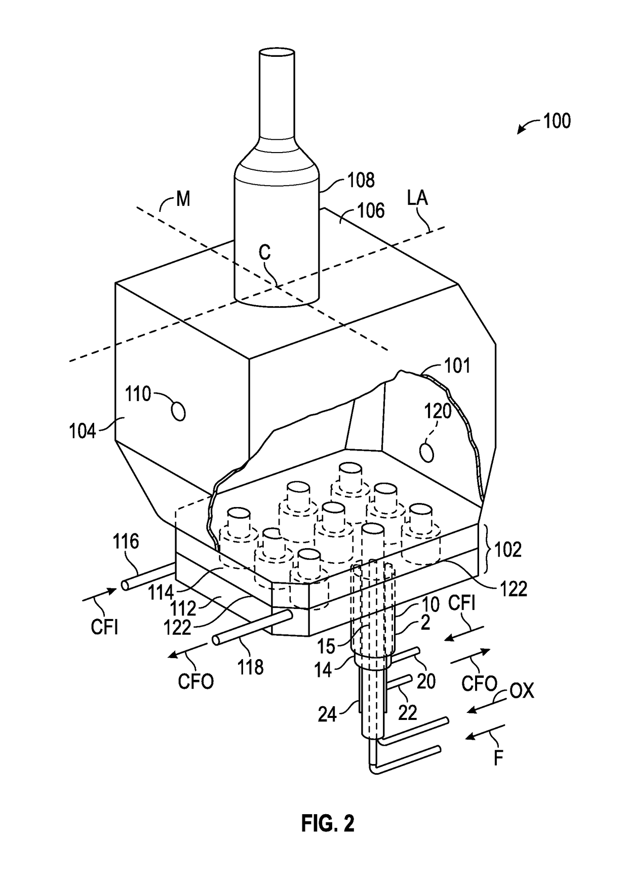
The present patent describes a submerged combustion melter (SCM) that has a floor, roof, and wall with at least one burner. The burner is protected from the molten glass produced by the melter by a cover material made of hard brick or refractory. This cover material also allows for the free flow of combustion products from the burner. The technical effect of this is reduced thermal fatigue and flame impingement on the burner tips, as well as reduced accretion formation and improved flame stability during operation of the SCM.

Problems solved by technology

The introduction of high flow rates of products of combustion of the oxidant and fuel into the molten material, and the expansion of the gases during submerged combustion (SC), cause rapid melting of the feedstock or portions thereof and much turbulence and foaming.
However, being expensive alloys, it is not presently economical to fabricate the entire burner using these materials, and it would be advantageous to eliminate use of noble metals altogether.
Without the presence of the SC burner cover material, accretions may form on SC burner tips during operation of the SCM causing deflection of flames therefrom, and in extreme cases onto neighboring SC burners or the melter refractory.

Method used


Image

  • Submerged combustion melters, wall structures or panels of same, and methods of using same
  • Submerged combustion melters, wall structures or panels of same, and methods of using same
  • Submerged combustion melters, wall structures or panels of same, and methods of using same

Examples


Embodiment Construction

[0021]In the following description, numerous details are set forth to provide an understanding of the disclosed burner panels, SCMs, and methods. However, it will be understood by those skilled in the art that the apparatus and methods covered by the claims may be practiced without these details and that numerous variations or modifications from the specifically described embodiments may be possible and are deemed within the claims. For example, wherever the term “comprising” is used, embodiments and / or components where “consisting essentially of” and “consisting of” are also explicitly disclosed herein and are part of this disclosure. An example of “consisting essentially of” may be with respect to the composition of a burner conduit: a conduit consisting essentially of carbon steel means there may be a minor portions or trace amounts of metals, oxides, and other chemical species that are noble metals, such chromium, platinum, and the like, and a conduit consisting essentially of n...


PUM

PropertyMeasurementUnit
angleaaaaaaaaaa
cone angleaaaaaaaaaa
anglesaaaaaaaaaa

Abstract

Submerged combustion burner panels, submerged combustion melters including one or more of the panels, and methods of using the same. The burner panel includes a panel body including a fluid-cooled portion and a protective non-fluid cooled portion. An exterior surface defined by the fluid-cooled portion, and an interior surface defined by the protective non-fluid cooled portion, exterior and interior referring to an SCM in which the panel is installed. The fluid-cooled portion has at least one burner support passage of diameter (d1) extending from the exterior surface to a seam where the fluid-cooled and protective non-fluid cooled portions meet supporting at least one fluid-cooled SC burner having a fluid-cooled burner tip attached to a burner body protruding away from the seam. The protective non-fluid-cooled portion has a combustion products flow passage of diameter (d2)<(d1). The burner panels promote burner life and melter campaign length.

Description

BACKGROUND INFORMATIONTechnical Field[0001]The present disclosure relates generally to the field of submerged combustion melters, submerged combustion burners and burner panels, and methods of use, particularly for melting glass-forming materials, mineral wool forming materials, rock wool forming materials and other non-metallic inorganic materials.Background Art[0002]A submerged combustion melter (SCM) may be employed to melt glass batch and / or waste glass materials to produce molten glass, or may melt minerals or rock feedstock to make mineral or rock wool, by passing oxygen, oxygen-enriched mixtures, or air along with a liquid, gaseous and / or particulate fuel (some of which may be in one or more of the feedstock materials), directly into a molten pool of glass or other material, usually through burners submerged in a turbulent melt pool. The introduction of high flow rates of products of combustion of the oxidant and fuel into the molten material, and the expansion of the gases d...

Claims


Application Information

Patent Timeline
Patent Type & Authority Applications(United States)
IPC IPC(8): C03B5/235C03B5/44
CPCC03B5/2356C03B2211/60C03B2211/22C03B5/44C03B5/167F23D14/22F23D14/76F23D14/78Y02P40/50
Inventor FAULKINBURY, ALBERT PATRICK
Owner JOHNS MANVILLE CORP
Learn More