Fluorescence microscope light source apparatus and fluorescence microscope

a fluorescence microscope and light source technology, applied in the field of fluorescence microscope light source apparatus and fluorescence microscope, can solve the problems of increasing background noise when a sample is observed, inability to provide high luminance at present, and difficulty in obtaining sufficient brightness in the field of view of the fluorescence microscope, so as to reduce background noise when the sample is observed

Inactive Publication Date: 2018-03-08
USHIO DENKI KK
View PDF0 Cites 2 Cited by
  • Summary
  • Abstract
  • Description
  • Claims
  • Application Information

AI Technical Summary

Benefits of technology

[0020]The fluorescence microscope light source apparatus according to the present invention includes the phosphor that converts the excitation light emitted by the laser diode into the illumination fluorescence with the wavelength region of 500 to 550 nm, and thus can emit high-luminance light in a wavelength of 500 to 550 nm. Furthermore, the band-elimination filter that blocks or attenuates light, out of the illumination fluorescence, in the wavelength region including the transmission maximum wavelength and including no transmission minimum wavelength in the illumination light bandpass filter is provided on the light path of the illumination fluorescence. Consequently, a wavelength region in which a sensitive spectrum and the fluorescence spectrum of a fluorescent dye overlap with each other is small, thus reducing the background noise when the sample is observed.

Problems solved by technology

When solid light-emitting elements are used as light sources, however, a solid light-emitting element that emits light with a wavelength of 500 to 550 nm, out of three types of solid light-emitting elements that emit red, green and blue light, cannot provide high luminance at present.
Thus, it is difficult to obtain sufficient brightness in the field of view of the fluorescence microscope.
However, it has been found out that problems as described below arise when such a light source apparatus is employed as a light source apparatus installed in a fluorescence microscope.
Consequently, a wavelength region in which the sensitive spectrum and the fluorescence spectrum of the fluorescent dye overlap with each other is increased, thus disadvantageously increasing background noise when a sample is observed.

Method used


Image

  • Fluorescence microscope light source apparatus and fluorescence microscope
  • Fluorescence microscope light source apparatus and fluorescence microscope
  • Fluorescence microscope light source apparatus and fluorescence microscope

Examples


Embodiment Construction

[0031]A fluorescence microscope light source apparatus (hereinafter referred to simply as a “light source apparatus”) according to an embodiment of the present invention will now be described below.

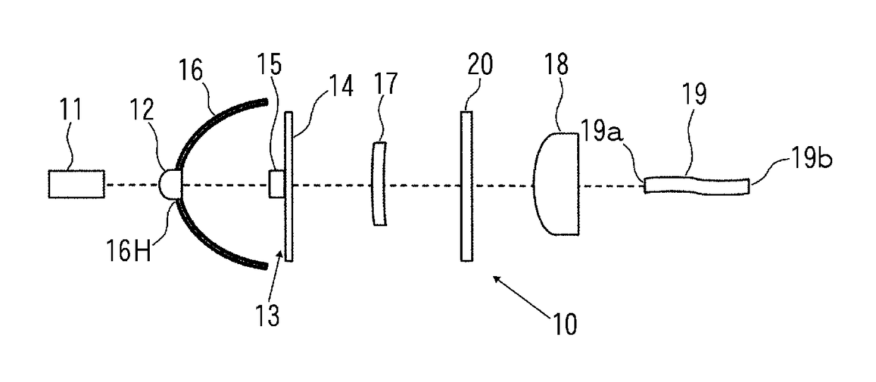
[0032]FIG. 1 is an explanatory diagram illustrating an exemplary configuration of a light source apparatus according to the present invention. A light source apparatus 10 shown in FIG. 1 is installed in a fluorescence microscope. Here, the fluorescence microscope includes an illumination light bandpass filter, and is configured to illuminate a sample with light with a wavelength of 500 to 550 nm having transmitted through the illumination light bandpass filter, and to observe observation fluorescence emitted by the sample.

[0033]The light source apparatus 10 includes a laser diode 11 that emits blue light as excitation light. A wavelength conversion member 13 is disposed in front of (the right side in FIG. 1) the laser diode 11 so as to face the laser diode 11. The wavelength conversion me...


PUM


Abstract

Disclosed are a fluorescence microscope light source apparatus and a fluorescence microscope capable of obtaining high-luminance light in a wavelength of 500 to 550 nm and having reduced background noise when a sample is observed. The fluorescence microscope light source apparatus to be installed in a fluorescence microscope including an illumination light bandpass filter includes: a laser diode that emits blue light as excitation light; a phosphor that converts the excitation light from the laser diode into illumination fluorescence with a wavelength region of 500 to 550 nm; an optical system that extracts the illumination fluorescence from the phosphor; a first condenser lens that condenses the excitation light onto the phosphor; a light guide body having one end face on which the illumination fluorescence is incident and the other end face from which the illumination fluorescence exits; and a second condenser lens that condenses the illumination fluorescence onto the one end face of the light guide body. A band-elimination filter that blocks or attenuates light, out of the illumination fluorescence, in a wavelength region including a transmission maximum wavelength and including no transmission minimum wavelength in the illumination light bandpass filter is provided on a light path of the illumination fluorescence.

Description

TECHNICAL FIELD[0001]The present invention relates to a fluorescence microscope light source apparatus and a fluorescence microscope.BACKGROUND ART[0002]As examples of a conventional light source to be installed in a fluorescence microscope, may be mentioned discharge lamps such as a short-arc ultrahigh pressure mercury lamp, a metal halide lamp and a xenon lamp. In addition, from the viewpoint of energy saving, downsizing of a device, increasing life of a light source and the like in recent years, using a solid light-emitting element such as a light-emitting diode as a light source has been proposed (see Patent Literature 1).[0003]When solid light-emitting elements are used as light sources, however, a solid light-emitting element that emits light with a wavelength of 500 to 550 nm, out of three types of solid light-emitting elements that emit red, green and blue light, cannot provide high luminance at present. Thus, it is difficult to obtain sufficient brightness in the field of v...

Claims


Application Information

Patent Timeline
Patent Type & Authority Applications(United States)
IPC IPC(8): G02B21/06G01J3/12F21K9/64
CPCG02B21/06G01J3/12G02B6/00G01J2003/1213G02B19/00F21K9/64G01J3/0227G01J1/58G01J3/10G01J3/4406G01J3/0208G01J3/024G01J3/0243G02B21/0032G02B21/0076G02B21/082G02B5/22G02B19/0052
Inventor TAKAKI, RYOHEIKABUKI, KIYOYUKI
Owner USHIO DENKI KK
Why Eureka
Try Eureka