Method and system for heat treatment of sheet metal

a technology of heat treatment and sheet metal, applied in the direction of heat treatment apparatus, manufacturing tools, furnaces, etc., can solve the problems of high strength, difficult design of equipment or hardware, and high requirements for wear resistance during use, so as to improve the quality of heating and enhance flexibility and control the heating process

Active Publication Date: 2018-03-15
IKERGUNE A I E
View PDF5 Cites 8 Cited by
  • Summary
  • Abstract
  • Description
  • Claims
  • Application Information

AI Technical Summary

Benefits of technology

[0082]Thus, the teachings of the present invention can be used to adequately control the heating when the effective spot moves over a curved surface, over a bent portion of the object, or when the effective spot moves from a first portion or region of the object to another portion or region placed at an angle with the first portion or region, etc. This can be very useful in order to, for example, assure a good quality of the heating, when the object being heated is an object that has previously been shaped (for example, hot-formed) in for example a press, so that the surface features a more or less complex shape with curves and / or bends, etc. This is often the case with, for example, sheet metal vehicle components.
[0083]The present invention provides for enhanced flexibility and control of the heating process, due to the way in which the two-dimensional energy distribution of the effective laser spot can be adapted without any need for modifying or replacing the optics involved.

Problems solved by technology

Crankshafts have complex surfaces and very high requirements on the resistance to wear during use.
It is explained that the high strength can render further operations on the hardened object, such as the establishment of perforations, difficult.
However, it appears that this frequently requires a complex design of the equipment or hardware used, and that modifications of the product and its characteristics, for example, in terms of the distribution of the regions or portions that feature different hardnesses, frequently requires substantial changes in the hardware used.
Also, when heating an object using an energy beam, changes in the angle between the beam and the surface portion being heated, for example, due to the shape of the object such as due to the presence of curvatures, bends, portions placed at an angle in relation to each other, etc., can give rise to difficulties or suboptimal quality of the heat treatment.

Method used


Image

  • Method and system for heat treatment of sheet metal
  • Method and system for heat treatment of sheet metal
  • Method and system for heat treatment of sheet metal

Examples


Embodiment Construction

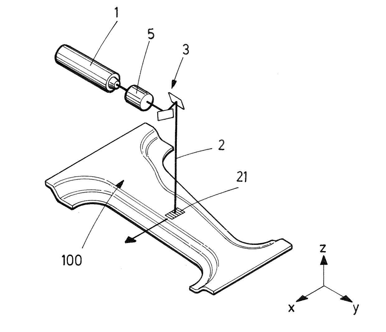
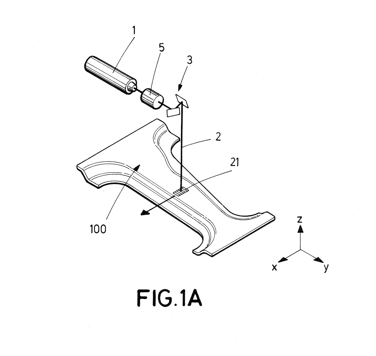
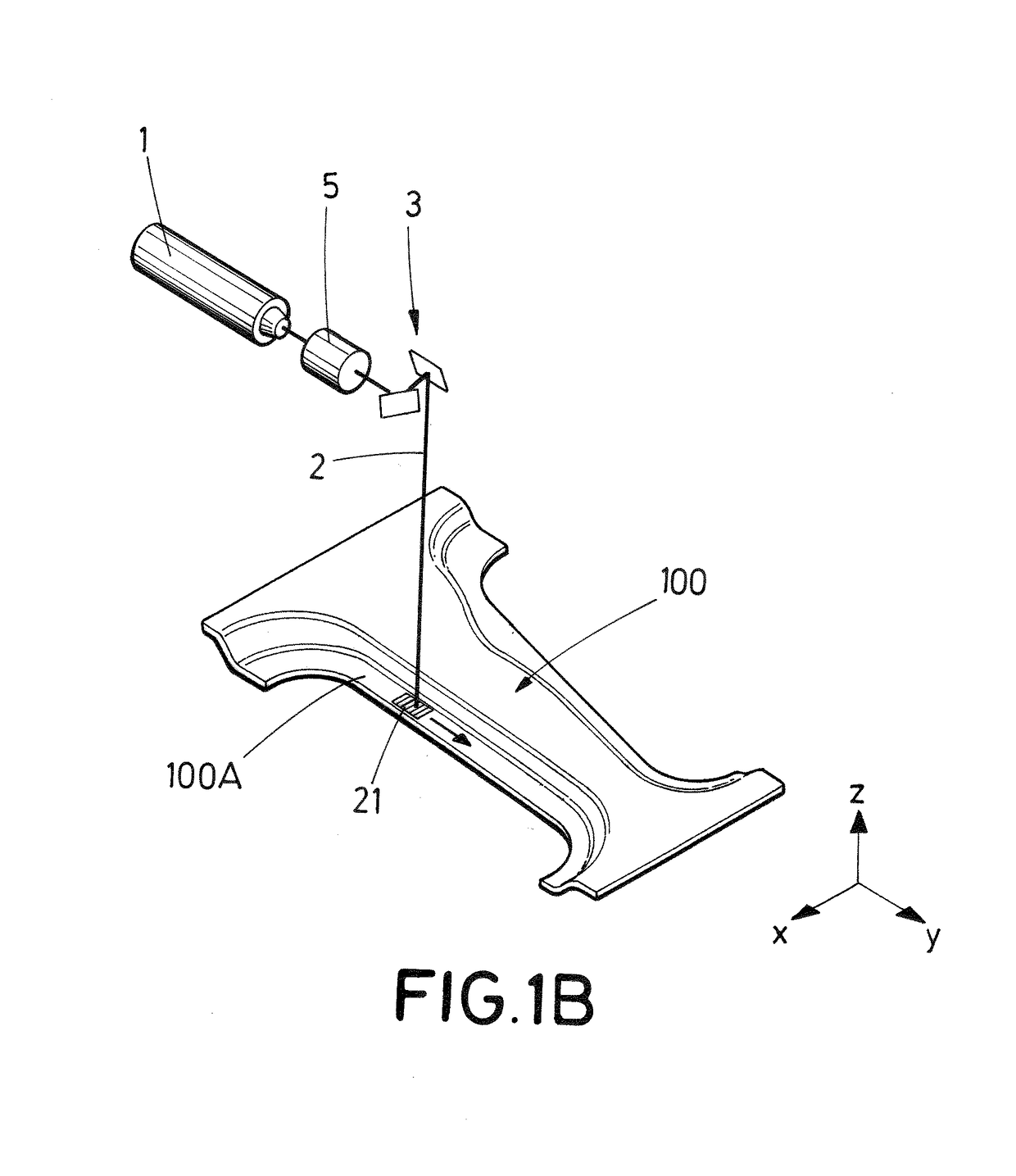
[0097]FIG. 1A schematically illustrates a system in accordance with one possible embodiment of the invention, for heat treatment of a sheet metal object such as a pillar for a vehicle. The system comprises a laser equipment 1 for producing a laser beam 2, and a scanner 3 including two mirrors or similar for two-dimensional scanning of the laser beam 2 in the horizontal (X-Y) plane. The equipment for producing a laser beam can, in some embodiments of the invention, be an equipment suitable for producing laser beams having a relatively high power content, such as 1 kW or more. One example of a suitable device is the Ytterbium Laser System Model YLS-6000-CT, by IPG Photonics, with a nominal power of 6 kW.

[0098]The system further comprises means (not shown in FIG. 1A) for holding or supporting a workpiece 100; in the illustrated embodiment, the workpiece is for a vehicle body pillar, such as a so-called center pillar. The pillar or pillar workpiece can, for example, be a workpiece with ...


PUM

PropertyMeasurementUnit
frequencyaaaaaaaaaa
frequencyaaaaaaaaaa
frequencyaaaaaaaaaa

Abstract

A method for heat treatment of an object of sheet metal, including heating at least one selected portion of the object using an energy beam, where the beam is projected onto a surface of the object so as to produce a primary spot on the object, the beam being repetitively scanned in two dimensions in accordance with a first scanning pattern so as to establish an effective spot on the object, the effective spot having a two-dimensional energy distribution, where the effective spot is displaced in relation to the surface of the object to progressively heat said at least one selected portion of the object.

Description

TECHNICAL FIELD[0001]The present invention relates to the heat treatment of sheet metal, for example, sheet metal for use in or used in metal products, for example, in structural components for vehicles, such as motor vehicles.BACKGROUND[0002]It is known in the art to subject metal to heat treatment. For example, it is well known in the art to harden ferrous materials, such as steel (for example, medium carbon steel), by heating the material to a high temperature, below its melting temperature, and subsequently quenching it, that is, cooling it rapidly enough to form hard martensite. Heating can take place in furnaces or by induction heating, and cooling can take place by applying a cooling fluid, such as water or water mixed with other components. It is also known to use laser light for carrying out certain hardening process, for example, in relation to complex products such as crankshafts. Crankshafts have complex surfaces and very high requirements on the resistance to wear durin...

Claims


Application Information

Patent Timeline
Patent Type & Authority Applications(United States)
IPC IPC(8): B23K26/00C21D9/46C21D1/09
CPCB23K26/0087C21D9/46C21D1/09C21D2221/00B23K2201/006C21D10/005C21D10/00C21D9/48C21D1/673C21D2221/02B23K26/082B23K2101/006Y02P10/25B23K26/359B23K26/073
Inventor SANCHO D AZ, PAULAD AZ ROZO, JAVIERDOM NGUEZ COBREROS, JES S
Owner IKERGUNE A I E
Why Eureka
Try Eureka