Inertial wave energy converter

a technology of energy converter and inertial wave, which is applied in the direction of fluid gearing, machine/engine, fluid gearing, etc., can solve the problems of limiting the location of these converters and the depth of water, reducing the efficiency of the device, and reducing the cost of manufacturing, operating and maintaining these devices. , to achieve the effect of high energy conversion efficiency, cost-effectiveness and longevity of mechanical components

Active Publication Date: 2018-03-15
LONE GULL HLDG LTD
View PDF13 Cites 9 Cited by
  • Summary
  • Abstract
  • Description
  • Claims
  • Application Information

AI Technical Summary

Benefits of technology

[0006]Disclosed is a novel ocean wave energy converter (“converter”) designed to cost-effectively achieve a high energy conversion efficiency. Moreover, the converter of the present invention exhibits a range of features designed to ensure survival during storms, the longevity of mechanical components, and a low cost of manufacture. The converter of the present disclosure will be characterized by a minimal environmental impact, as well as an ability to optimize system behavior and performance with respect to changing wave conditions.

Problems solved by technology

However, solving this latter problem has been challenging and the few existing operational wave to energy converters share several major shortcomings.
This requirement limits the location of these converters and the depth of the water in which they may be deployed.
The amounts of energy that can be extracted from devices of the prior art are meager compared with the expense of fabricating, operating, and maintaining these devices.
However, the prior art lacks an effective manner or technology with which to accomplish this goal.

Method used


Image

  • Inertial wave energy converter
  • Inertial wave energy converter
  • Inertial wave energy converter

Examples


embodiment 130

[0400]FIG. 23 shows a top-down view of an embodiment 130 similar to the one illustrated in FIG. 22. The only difference between the embodiments illustrated in FIGS. 22 and 23 is that the embodiment illustrated in FIG. 23 has eight cables, traction winches, and PTOs, whereas (for the sake of graphical clarity) the embodiment illustrated in FIG. 22 was limited to two cables, traction winches, and PTOs.

[0401]Eight cables, e.g. 133 connect the buoy to the submerged inertial mass (132 in FIG. 22). Each cable, e.g. 133, passes over and around a directional rectifying pulley, e.g. 138, and then passes through the hollow connecting arm, e.g. 143, that hold each respective directional rectifying pulley and allows it to rotate, by means of a respective bearing, e.g. 144, about the longitudinal and / or rotational axis of its respective hollow connecting arm, e.g. 143.

[0402]Each cable, e.g. 146, exits the hollow connecting arm, e.g. 143, and passes onto, around, and over a pair of cooperating tr...

embodiment 100

[0759]The illustrated embodiment 100 receives tasks, programs, data, messages, signals, information, and / or digital values, emitted 112, issues, and / or transmitted, from at least one satellite 111, at least in part, through antenna 110, the data having, at least in part, originated from a remote computer and / or server.

[0760]The illustrated embodiment 100 transmits 113, communicates, emits, and / or issues, data, task results, messages, signals, information, status updates, and / or digital values, at least in part, from antenna 110, which are subsequently received, at least in part, by satellite 111, which may then transmit that received data to a remote computer and / or server.

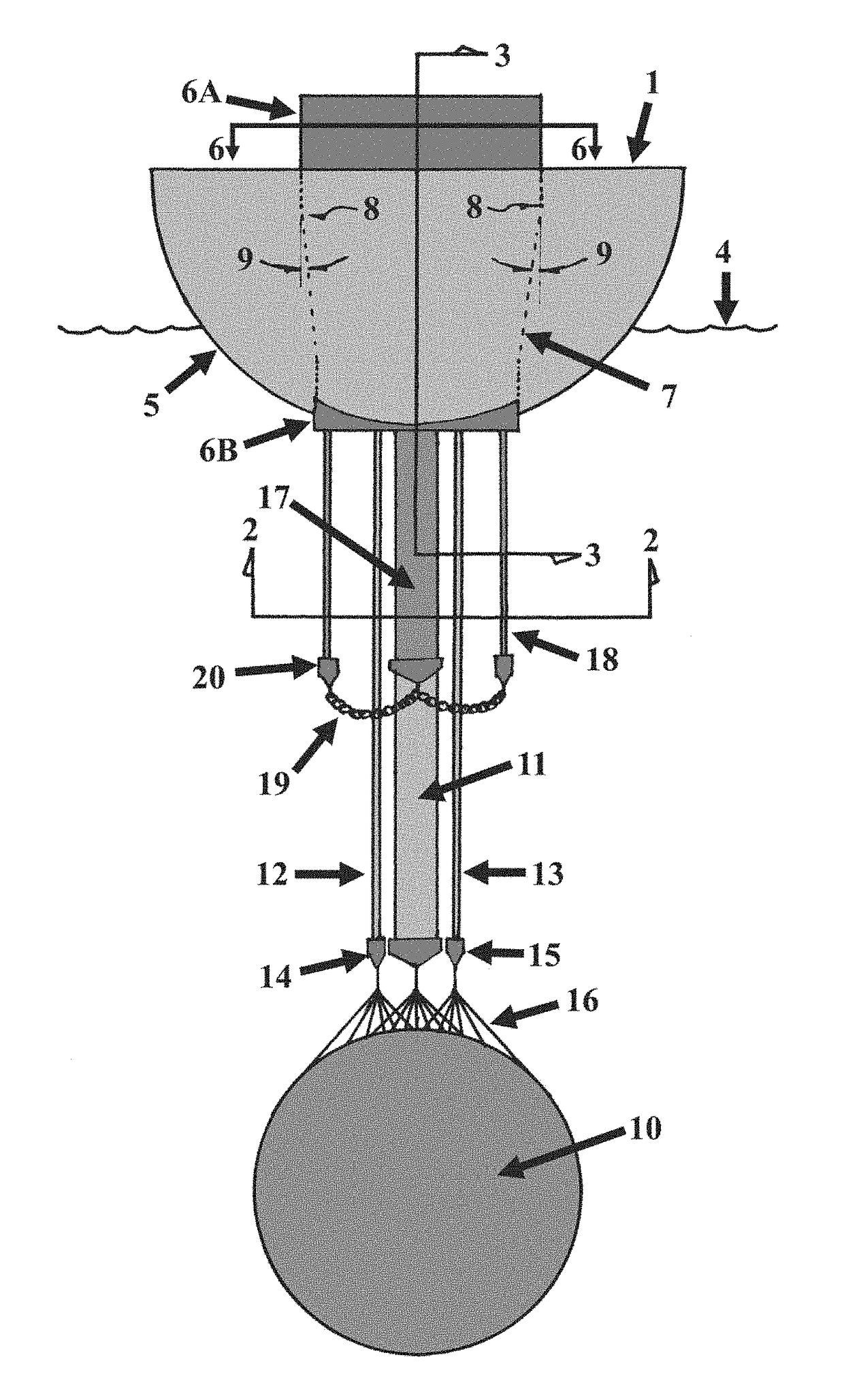
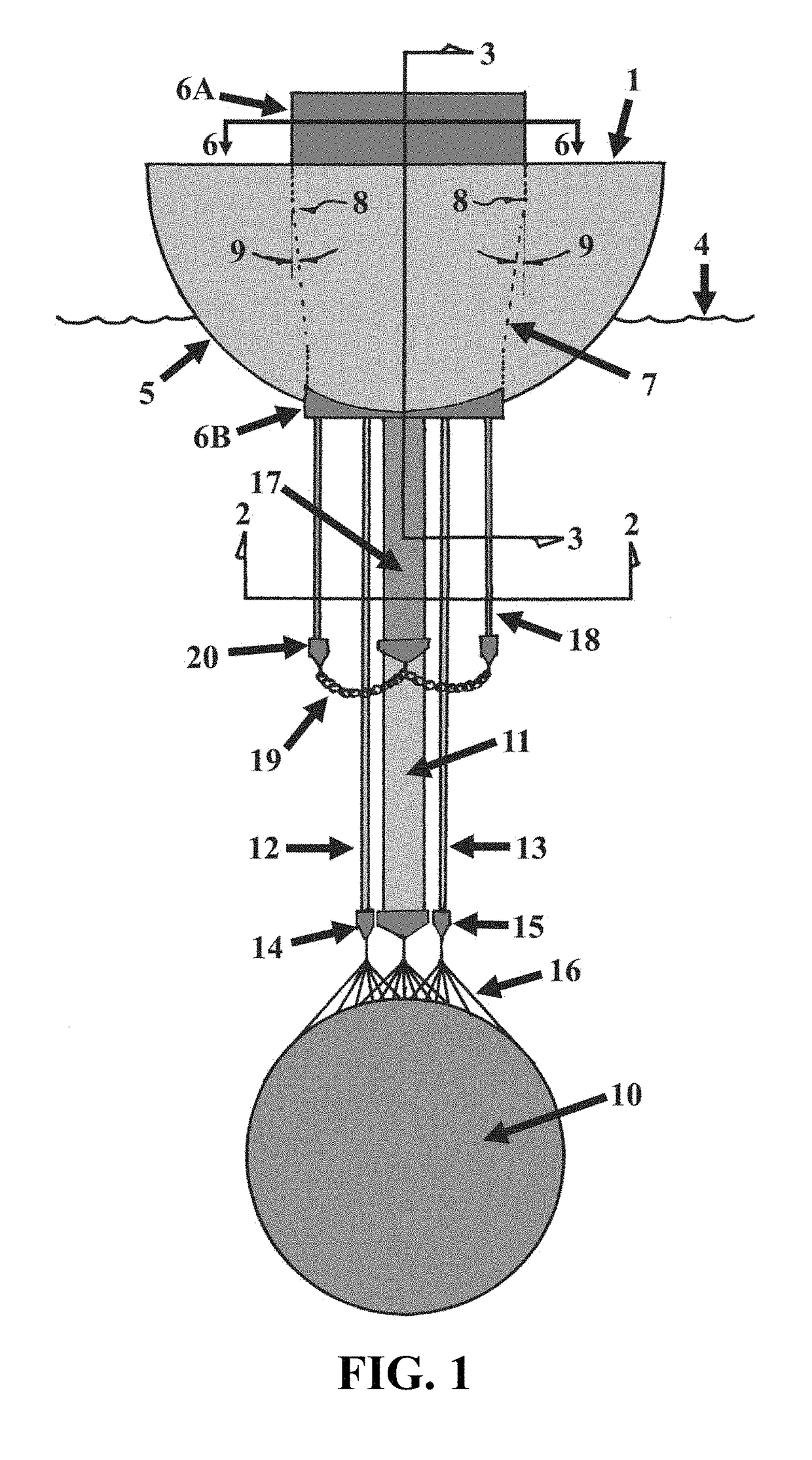
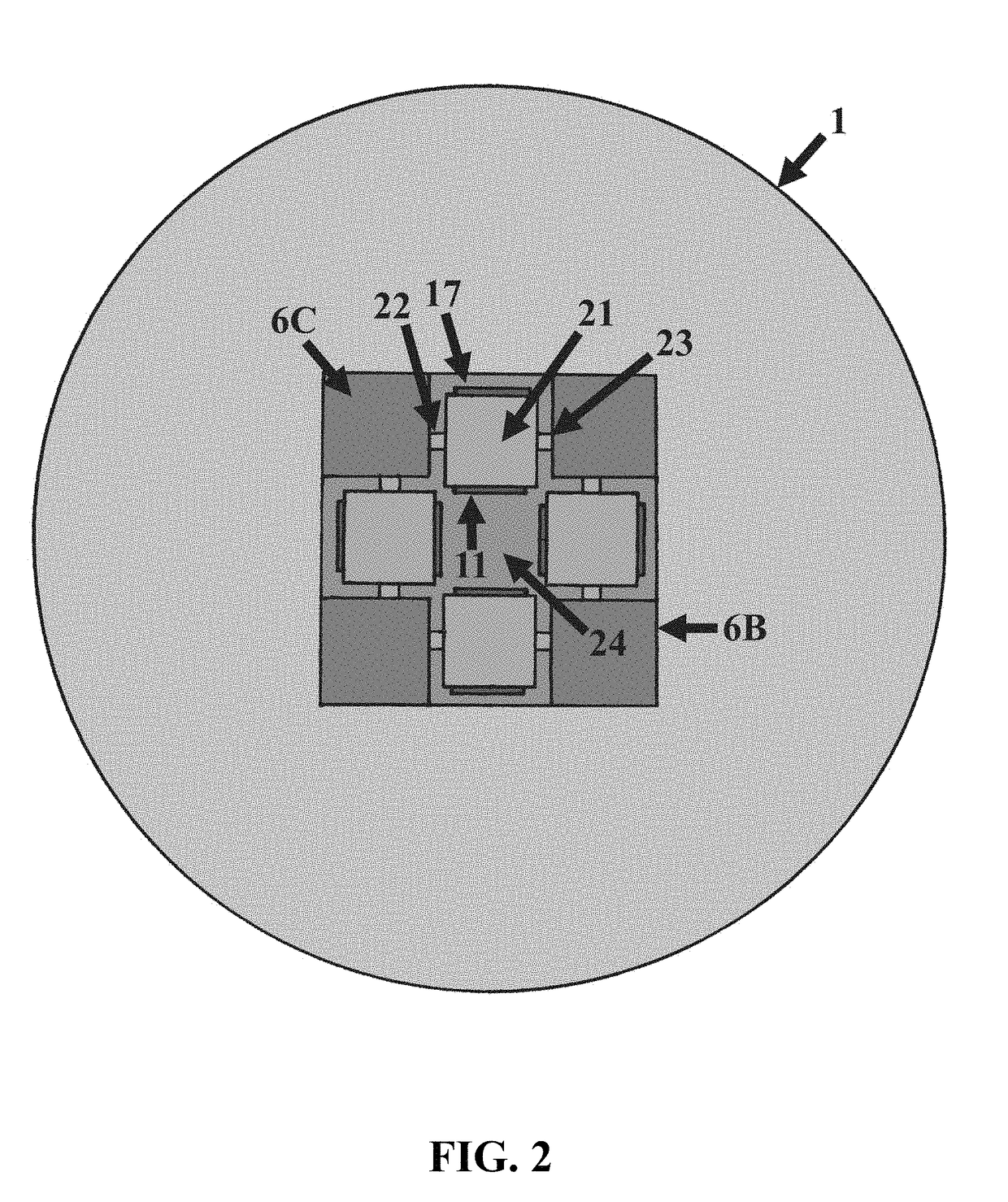
[0761]FIG. 136 shows a top-down view of the same embodiment of the current disclosure illustrated in FIG. 135. A buoy 100 floats adjacent to the surface of a body of water. Attached to, mounted on, and / or incorporated within, the buoy 100 is a power take-off (PTO) 102, and / or electrical power-generation assembly. ...

embodiment 720

[0826]FIG. 158 shows a perspective view of an embodiment 720 of the current disclosure. This embodiment utilizes a stacked and / or vertically-aligned set of plates 732-735.

[0827]FIG. 159 shows a perspective view of an embodiment of the current disclosure.

[0828]This embodiment is similar in most respects to the embodiment of FIG. 54, but its inertial mass is different.

[0829]Inertial mass 8-140 encloses, confines, and / or traps a large volume of water but need not have any rigid walls. It can be collapsible for manufacture, transportation, and the early stages of deployment. It can assume its full volume only upon final deployment, when the inertial mass weighted portion 8-200 pulls it into tension vertically and thereby extends its frustoconical regions, allowing it to assume a form having a large volume and enclosing a large volume of water. It is presumed that rigid circumferential ribs or “spacers” are required down the length of the cone to keep the structure “open” during operatio...


PUM


Abstract

A wave energy converter generates power from a wave-induced separation of a positively buoyant flotation module and a submerged negatively buoyant mass, using a rotating pulley to drive a power-take-off system.

Description

CROSS-REFERENCES TO RELATED APPLICATIONS[0001]This application claims priority from U.S. Ser. No. 62 / 536,221, filed Jul. 24, 2017; U.S. Ser. No. 62 / 533,058, filed Jul. 16, 2017; U.S. Ser. No. 62 / 506,636, filed May 16, 2017; U.S. Ser. No. 62 / 506,015, filed May 15, 2017; U.S. Ser. No. 62 / 482,693, filed Apr. 7, 2017; U.S. Ser. No. 62 / 452,388, filed Jan. 31, 2017; U.S. Ser. No. 62 / 441,457, filed Jan. 2, 2017; U.S. Ser. No. 62 / 436,479, filed Dec. 20, 2016; U.S. Ser. No. 62 / 435,895, filed Dec. 19, 2016; U.S. Ser. No. 62 / 430,354, filed Dec. 6, 2016; U.S. Ser. No. 62 / 426,328, filed Nov. 25, 2016; and U.S. Ser. No. 62 / 393,056, filed Sep. 11, 2016, the contents of which are each fully incorporated herein by reference in their entirety.BACKGROUND[0002]The attempts to recover useful energy from the motion of waves on a body of water are well documented. Proposed devices for converting the reciprocating action of buoyant objects on the surface of a body of water into electrical power are replete...

Claims


Application Information

Patent Timeline
Patent Type & Authority Applications(United States)
IPC IPC(8): F03B13/14H02K7/18F03B13/22
CPCF03B13/148H02K7/1853F03B13/22F03B13/14F03B13/1885F03B13/20H02K3/52Y02E10/30F03B13/12F03B13/16F03B13/26F03B13/264F16H19/06F16H39/00F16H41/00Y02E10/20
Inventor SHELDON-COULSON, GARTH ALEXANDERMOFFAT, BRIAN LEEPLACE, DANIEL WILLIAMSHALHOUB, RABEH BASSAM
Owner LONE GULL HLDG LTD
Why Eureka
Try Eureka