Electromagnetic shielding material
- Summary
- Abstract
- Description
- Claims
- Application Information
AI Technical Summary
Benefits of technology
Problems solved by technology
Method used
Image
Examples
example
[0059]Examples of the present invention are described below together with comparative examples, which are provided for a better understanding of the present invention and its advantages, and are not intended to limit the invention.
[0060]Each metal foil and each insulating film as shown in Table 2 were prepared and electromagnetic shielding materials of Examples and Comparative Examples were produced. Each symbol described in Table 2 has the following meanings. The conductivity of the metal foil was measured by the double bridge method according to JIS C2525: 1999. The relative dielectric constant was measured by the B method according to JIS C2151: 2006.
Cu: rolled copper foil (conductivity at 20° C.: 58.0×10⁶ S / m);
Al: aluminum foil (conductivity at 20° C.: 39.6×10⁶ S / m);
Electrolytic Cu: electrolytic copper foil (conductivity at 20° C.: 56.0×10⁶ S / m);
Ni: nickel foil (conductivity at 20° C.: 14.5×10⁶ S / m);
Fe: soft iron foil (conductivity at 20° C.: 9.9×10⁶ S / m);
examples 1 , 3 to 13
Examples 1, 3 to 13, and 15 to 20
[0068]The insulating film(s) having the thickness and type as shown in Table 2, as well the metal foils each having the thickness and type as shown in Table 2 were simply laminated without using an adhesive to produce an electromagnetic shielding material having a laminated structure as described in Table 2. Each metal foil was used after removing metal oxides by degreasing and acid-washing the surface. The thickness of the metal oxide layer was adjusted by changing the concentration of the acid used for washing (for the washing with the acid, the concentration of an aqueous H2 SO4 solution was changed from 5 to 100 g / L) and the washing time (changed from 1 to 60 seconds) in each Example. The electromagnetic shielding material was set to the magnetic field shielding effect evaluation apparatus (Model TSES-KEC available from Techno Science Japan Co., Ltd.) and the magnetic field shielding effect was evaluated by the same method as described in Compara...
example 2 , 14
Example 2, 14
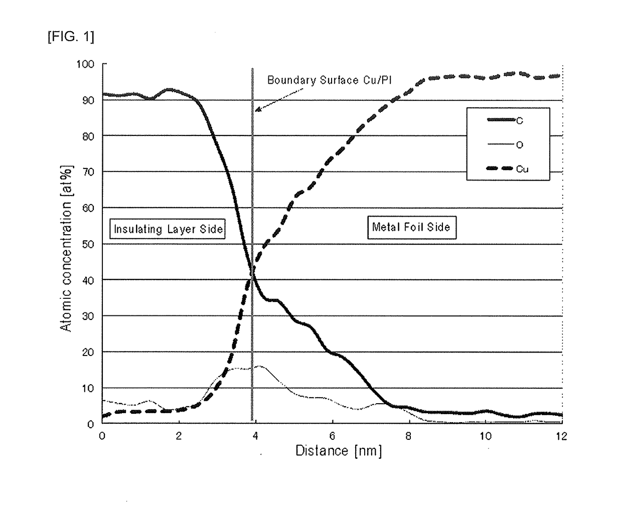
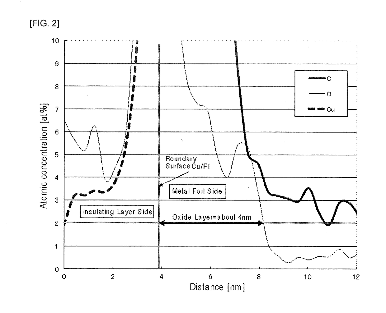
[0070]The insulating film having the thickness and type as shown in Table 2, as well the metal foils each having the thickness and type as shown in Table 2 were laminated using adhesives (a main agent RU-80 and a curing agent H-5, available from ROCK BOND) to produce an electromagnetic shielding material having a laminated structure as described in Table 2. Each metal foil was used after removing metal oxides by degreasing and acid-washing the surface. The thickness of the metal oxide layer was adjusted by changing the concentration of the acid used for washing and the washing time in each Example. The electromagnetic shielding material was set to the magnetic field shielding effect evaluation apparatus (Model TSES-KEC available from Techno Science Japan Co., Ltd.) and the magnetic field shielding effect was evaluated by the same method as described in Comparative Example 1. Further, after exposing the cross section of each electromagnetic shielding material by FIB (Foc...
PUM
| Property | Measurement | Unit |
|---|---|---|
| Temperature | aaaaa | aaaaa |
| Thickness | aaaaa | aaaaa |
| Thickness | aaaaa | aaaaa |
Abstract
Description
Claims
Application Information
 - R&D
- Intellectual Property
- Life Sciences
- Materials
- Tech Scout
- Unparalleled Data Quality
- Higher Quality Content
- 60% Fewer Hallucinations
Browse by: Latest US Patents, China's latest patents, Technical Efficacy Thesaurus, Application Domain, Technology Topic, Popular Technical Reports.
© 2025 PatSnap. All rights reserved.Legal|Privacy policy|Modern Slavery Act Transparency Statement|Sitemap|About US| Contact US: help@patsnap.com


