
Anti-penetration bone implant device and method

a bone implant and anti-penetration technology, applied in the field of bone implant devices and methods, can solve the problems of reduced implant ability, high fracture rate, and insufficient secure attachment of implant screws or other similar fixation devices, and achieve the effect of being convenient, inexpensive, and highly effectiv

Active Publication Date: 2018-03-29
VERSITECH LTD
View PDF6 Cites 11 Cited by
  • Summary
  • Abstract
  • Description
  • Claims
  • Application Information

AI Technical Summary

Benefits of technology

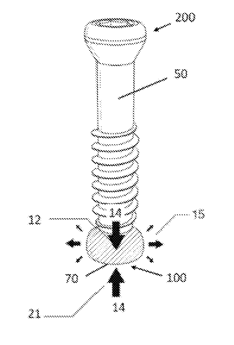
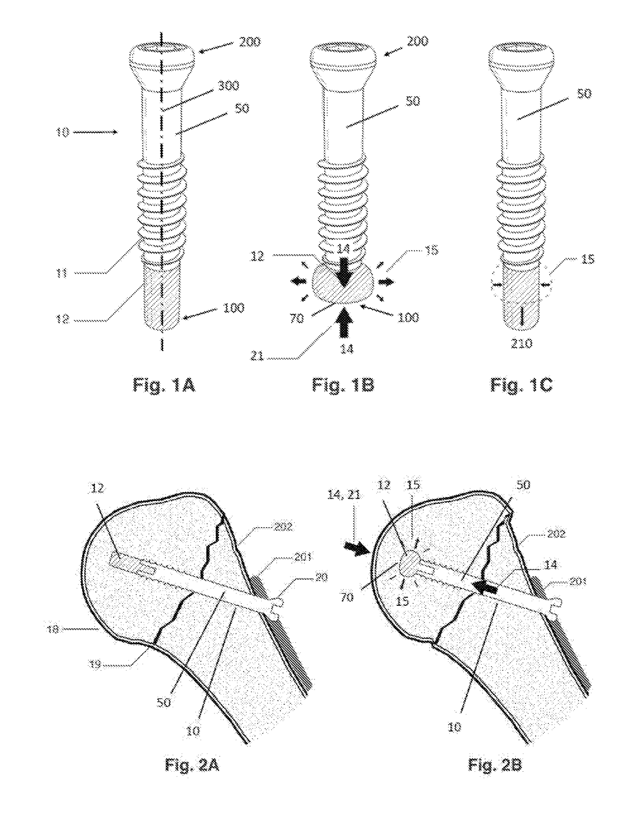
This patent is about an improvement to bone implants that reduces the risk of complications and failure. The invention is a new type of bone screw that can deform and increase contact with the surrounding bone tissue, reducing stress and movement in the area around the implant. This results in better stability, reduced screw penetration, and improved outcomes for patients. The invention can be used with existing bone implants and is cost-effective.

Problems solved by technology

There exist numerous problems related to the biomechanical and biological properties of bone which may potentially reduce the ability of implants, such as orthopaedic implants, to satisfactorily treat musculoskeletal injuries, trauma and defects.
Such biomechanical problems are often related to, and exacerbated by, biological changes to the processes of bone generation and remodeling.
In individuals with osteoporosis, these bones often develop numerous cavities and cysts within the spongy tissue that can compromise structural strength and lead to higher fracture rates.
Osteoporotic bone, however, has a highly porous interior that is often too structurally weak and inadequate for the secure attachment of implant screws or other similar fixation devices.
Patients with osteoporosis who undergo internal fracture fixation often experience a complication known as “cut-out,” in which natural movement, bone shrinkage, or accidental injury can cause an implant screw or other embedded fixation device to penetrate through the bone and out into surrounding soft tissues.
In the case of the hip, shoulder, or spine, this frequently leads to severe trauma of the articular cartilage of the joint or intervertebral disc and requires surgical revision to correct.
Furthermore, all bone tissue, in particularly bone tissue already weakened by conditions such as osteoporosis, degenerative disorders, compromised bone stock, are susceptible to complications due to the migration and loosening of devices including implants, fixation devices and bone anchors.
Such migration of the device within the bone can cause instability of fracture site, aseptic loosening, increased stresses on implants and fixation devices which may precipitate fatigue and failure and upon bone anchors which may cause instability and potential loosening and pull-out, and other complications that reduce overall musculoskeletal health and integrity of bone tissue and bone stability.
As mentioned above, the presence of a device within bone stock may contribute to or cause weakness of the bone through mechanisms such as bone resorption due to stress shielding.

Method used


Image

  • Anti-penetration bone implant device and method
  • Anti-penetration bone implant device and method
  • Anti-penetration bone implant device and method

Examples


example 2

Artificial Bone Penetration Test 1

[0187]In FIG. 15B, there is shown the results of artificial bone penetration experiments, comparing the rates of penetration of bone screws featuring dynamically expanding tips with the rates of penetration of conventional blunt-tipped bone screws. These experiments, conducted by the inventors under controlled laboratory conditions based on standards detailed in ASTM F543, tested the penetration rate of 5 mm diameter bone screws placed in shallow 6 mm diameter pilot holes drilled into artificial bone testing material consisting of polyurethane foam blocks with a density of 0.16 g / cc (PU Block #10 produced by Sawbones™, Inc.). Each screw type (either conventional blunt-tipped steel alloy or steel alloy with dynamically expandable tip of silicone rubber foam), was loaded axially by biomechanical testing machine with a sinusoidal load of 50-135N at 1 Hz, until penetration of the screw through the artificial bone was recorded (representing approximately...

example 3

Artificial Bone Penetration Test 2

[0234]In FIG. 37, there is shown the results of synthetic bone tissue (Sawbones™ Type 10—0.16 g / cc rigid polyurethane foam, manufactured as a substrate for simulating the mechanical properties of human osteoporotic bone) penetration experiments, in which a comparison the rates of penetration of bone screws featuring dynamically expanding tips as provided by the current invention, with the rates of penetration of conventional bone screws, such rates of penetration being in common clinical use. These experiments, conducted by the inventors under controlled laboratory conditions based on standards detailed in ASTM F543, were utilized to determine the penetration rate of 5 mm diameter bone screws placed in shallow 6 mm diameter pilot holes drilled into the surfaces of the synthetic bone material.

[0235]Each screw type was loaded axially by use of an MTS™ a mechanical testing machine with a displacement rate of 5 millimeters per minute, until penetration ...

example 4

Artificial Bone Penetration Test 3

[0239]In FIG. 38, there is shown the results of synthetic bone tissue (Sawbones™ Type 10—0.16 g / cc rigid polyurethane foam, manufactured as a substrate for simulating the mechanical properties of human osteoporotic bone) penetration experiments, comparing the rates of penetration of bone screws including dynamically expanding tips of the current invention with the rates of penetration of conventional bone screws in common clinical use.

[0240]These experiments, conducted by the inventors under controlled laboratory conditions based on standards detailed in ASTM F543, provided for the testing of the penetration rate of 5 mm diameter bone screws placed in shallow 6 mm diameter pilot holes drilled into the surface of the synthetic bone material.

[0241]Each screw type, was loaded axially by way of an MTS™ mechanical testing machine with a displacement rate of 5 millimeters per minute, until penetration of the screw through the synthetic bone was achieved (...


PUM


Abstract

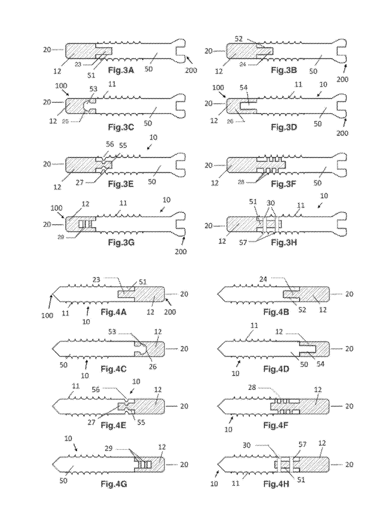
A device for engagement with a bone includes a dynamically expandable tip (12), a dynamically expandable ring (40), or other dynamically expandable insert (60, 62, 401L) that reacts to forces pushing the implant into bone tissue. The tip (12), ring (40) or insert (60, 62, 401L) expands at least normal to the direction of motion, increasing contact area between the surrounding bone tissue and the material and thereby reducing the occurrence of high areas of contact stress in the adjacent bone tissue. The tip (12), ring (40) or insert (60, 62, 401L) translates forces along an axis of motion into lateral frictional forces that can resist penetration into the bone tissue without the need for additional operator or patient interaction. A method of reducing migration of the device for engagement includes the steps of providing the device and inserting the device within bone tissue.

Description

BACKGROUND OF THE INVENTION[0001]There exist numerous problems related to the biomechanical and biological properties of bone which may potentially reduce the ability of implants, such as orthopaedic implants, to satisfactorily treat musculoskeletal injuries, trauma and defects. By way of example, implants such as bone screws, nails, and plates may weaken surrounding tissue through a mechanism known as stress shielding. In the case of another mechanism known as aseptic loosening, the fit between orthopedic implants and bone tissue may become looser over time as loading on the implant crushes and compacts adjacent bone tissue. During progressive cut out, an implant gradually penetrates through the bone until it breaks through the cortex entirely. Such biomechanical problems are often related to, and exacerbated by, biological changes to the processes of bone generation and remodeling. One common biological change is the loss of bone mass and structural strength due to imbalance in th...

Claims


Application Information

Patent Timeline
IPC IPC(8): A61B17/86A61B17/70
CPCA61B2017/044A61B2017/8655A61B17/86A61B17/7001A61B17/8635A61B2017/00862A61B2017/042A61B17/0401A61B17/8625A61B2017/00858A61B2017/0429A61B2017/0432A61B2017/0437A61B17/844
Inventor KULPER, SLOAN AUSTINLU, WILLIAM WEIJIALEUNG, FRANKIE KA LIFANG, CHRISTIAN XINSHUO
Owner VERSITECH LTD
Learn More