
Physical quantity measurement apparatus, electronic apparatus, and vehicle

a technology of physical quantity measurement and electronic equipment, applied in the direction of pulse characteristics measurement, pulse technique, instruments, etc., can solve the problems of difficult to achieve high-performance time-to-digital conversion and difficulty in improving accuracy, and achieve the effect of simplifying the time-to-digital conversion process and high perfor

Active Publication Date: 2018-03-29
SEIKO EPSON CORP
View PDF0 Cites 12 Cited by
  • Summary
  • Abstract
  • Description
  • Claims
  • Application Information

AI Technical Summary

Benefits of technology

This patent is about a device that can measure physical quantities, like electronic equipment and vehicles. The invention aims to improve the speed at which the device converts time to digital format, making it more effective or easier to use.

Problems solved by technology

However, in time-to-digital conversion using a semiconductor element, improvement of a resolution is easy, but there is a problem in that improvement of accuracy is not easy.
Thus, an appropriate control process on the two oscillation circuits cannot be performed, and, as a result, it is difficult to achieve high performance time-to-digital conversion.

Method used


Image

  • Physical quantity measurement apparatus, electronic apparatus, and vehicle
  • Physical quantity measurement apparatus, electronic apparatus, and vehicle
  • Physical quantity measurement apparatus, electronic apparatus, and vehicle

Examples


Embodiment Construction

[0090]Hereinafter, a preferred embodiment of the invention will be described with reference to the drawings. The present embodiment described below is not intended to limit the scope of the invention disclosed in the appended claims, and all constituent elements described in the embodiment are not essential constituent elements of the invention.

1. Physical Quantity Measurement Apparatus

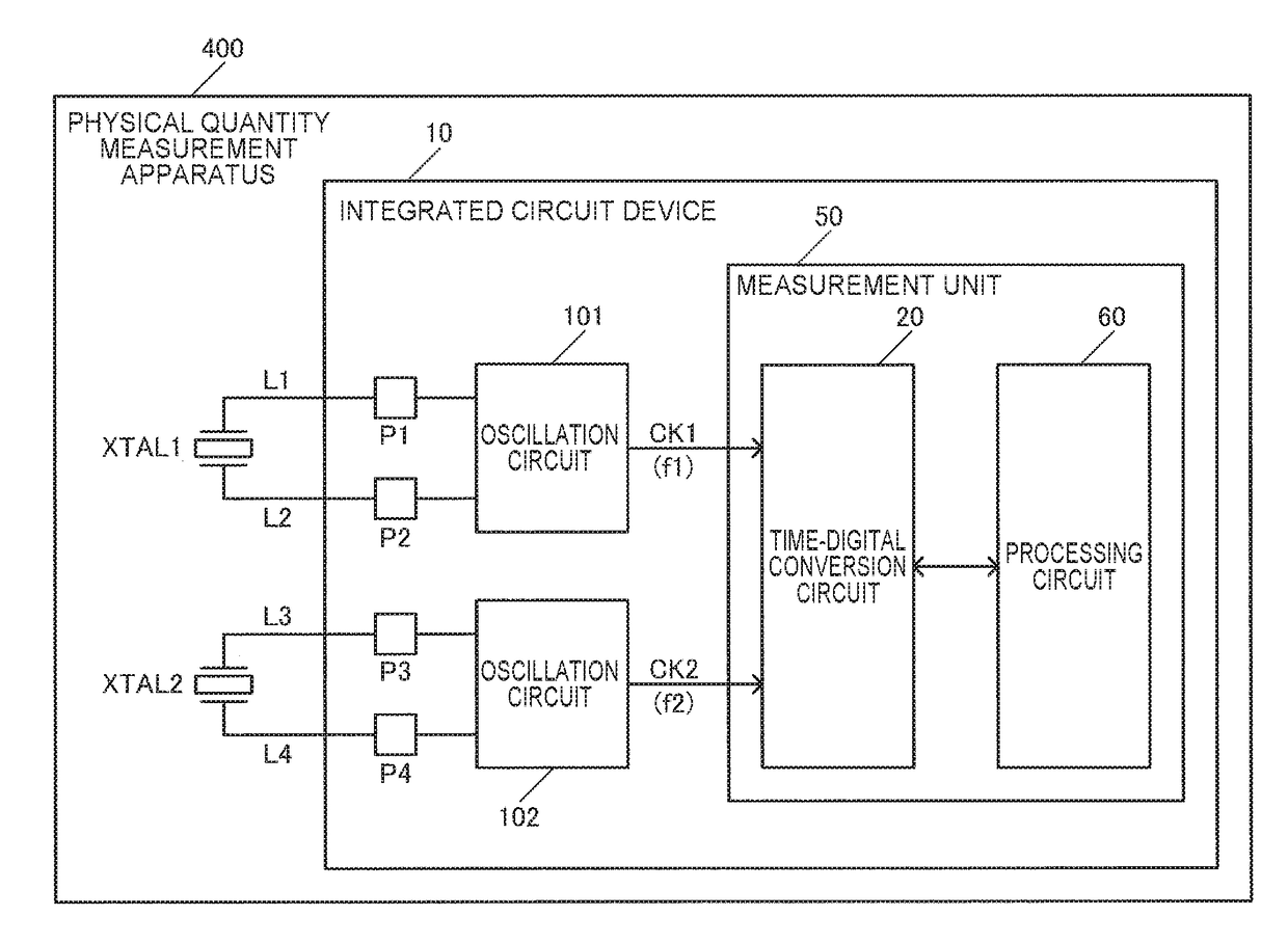
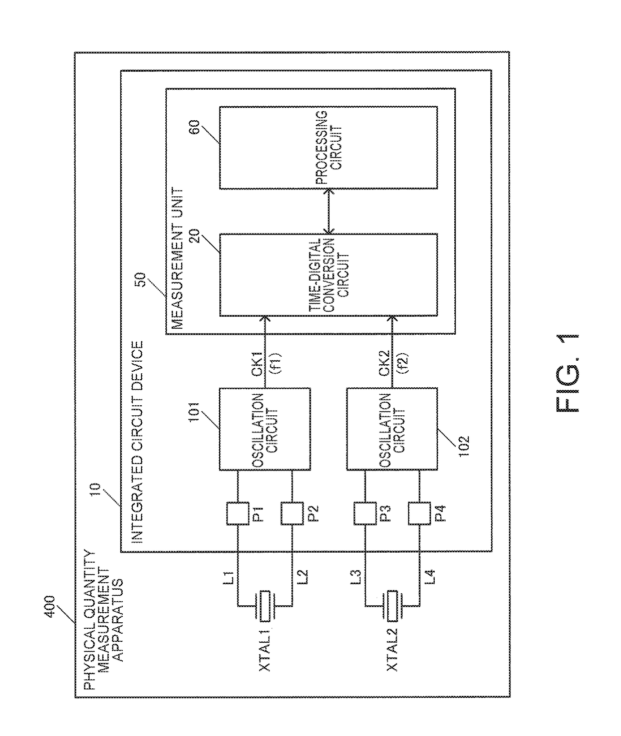
[0091]FIG. 1 illustrates a fundamental configuration example of a physical quantity measurement apparatus 400 according to the present embodiment. The physical quantity measurement apparatus 400 includes an oscillator XTAL1 (first resonator), an oscillator XTAL2 (second oscillator), and an integrated circuit device 10. Signal lines L1, L2, L3 and L4 or a package which will be described later may be included. However, the physical quantity measurement apparatus 400 is not limited to the configuration illustrated in FIG. 1, and maybe variously modified, for example, some of the constituent elements may ...


PUM


Abstract

A physical quantity measurement apparatus includes a first resonator, a second oscillator, and an integrated circuit device. The integrated circuit device includes a first oscillation circuit that causes the first resonator to oscillate, and thus generate a first clock signal having a first clock frequency, a second oscillation circuit that causes the second oscillator to oscillate, and thus generate a second clock signal having a second clock frequency which is different from the first clock frequency, and a measurement unit that is provided with a time-to-digital conversion circuit which converts time into a digital value by using the first clock signal and the second clock signal.

Description

BACKGROUND1. Technical Field[0001]The present invention relates to a physical quantity measurement apparatus, an electronic apparatus, a vehicle, and the like.2. Related Art[0002]In the related art, there are known time-to-digital conversion circuits. The time-to-digital conversion circuit converts time into a digital value. As examples of such time-to-digital conversion circuits of the related art, known techniques of the related art are disclosed in JP-A-2009-246484, JP-A-2007-110370, JP-A-2010-119077, and JP-A-5-87954.[0003]In the techniques of the related art disclosed in JP-A-2009-246484, JP-A-2007-110370, and JP-A-2010-119077, time-to-digital conversion is performed by using a so-called vernier delay circuit. The vernier delay circuit performs time-to-digital conversion by using a delay element which is a semiconductor element.[0004]JP-A-5-87954 discloses a minute time measurement apparatus including a first quartz crystal oscillator outputting a first clock pulse, a second qu...

Claims


Application Information

Patent Timeline
IPC IPC(8): G01R23/10G01R29/02G04F10/04H03K21/02G04F10/00
CPCG04F10/04H03K21/023G04F10/005G01R23/10G01R29/02G01D5/26G01R23/12
Inventor MAKI, KATSUHIKOHANEDA, HIDEOKURASHINA, TAKASHITSUTSUMI, AKIOSUDO, YASUHIRO
Owner SEIKO EPSON CORP
Learn More