Sieve array and precipitator device and method of treating exhaust

Active Publication Date: 2018-05-03
OHIO UNIV
View PDF0 Cites 2 Cited by
  • Summary
  • Abstract
  • Description
  • Claims
  • Application Information

AI Technical Summary

Benefits of technology

[0006]The objective of this invention is to use an array of wet vibrating cords (cylinders or ropes) to capture particulates from a hot gas stream along with efficient energy recovery. When particulate-laden hot gas flows through an array of vertical wet cords, they tend to vibrate due to vortex shedding. In particular, the cords will have vibrations primarily perpendicular to the flow direction and less pronounced ones in the flow direction. In t

Problems solved by technology

When particulate-laden hot gas flows through an array of ver

Method used


Image

  • Sieve array and precipitator device and method of treating exhaust
  • Sieve array and precipitator device and method of treating exhaust
  • Sieve array and precipitator device and method of treating exhaust

Examples


example

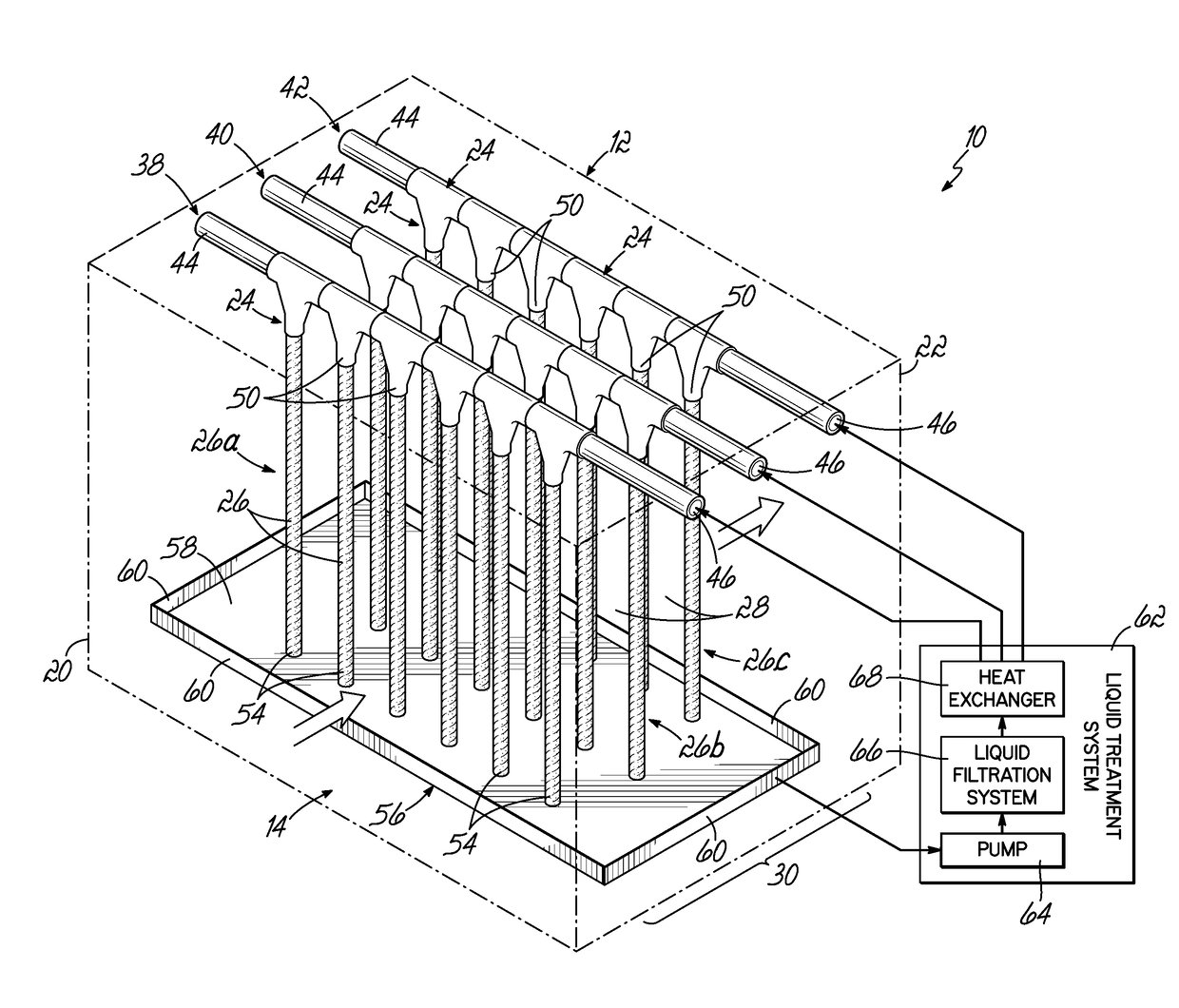
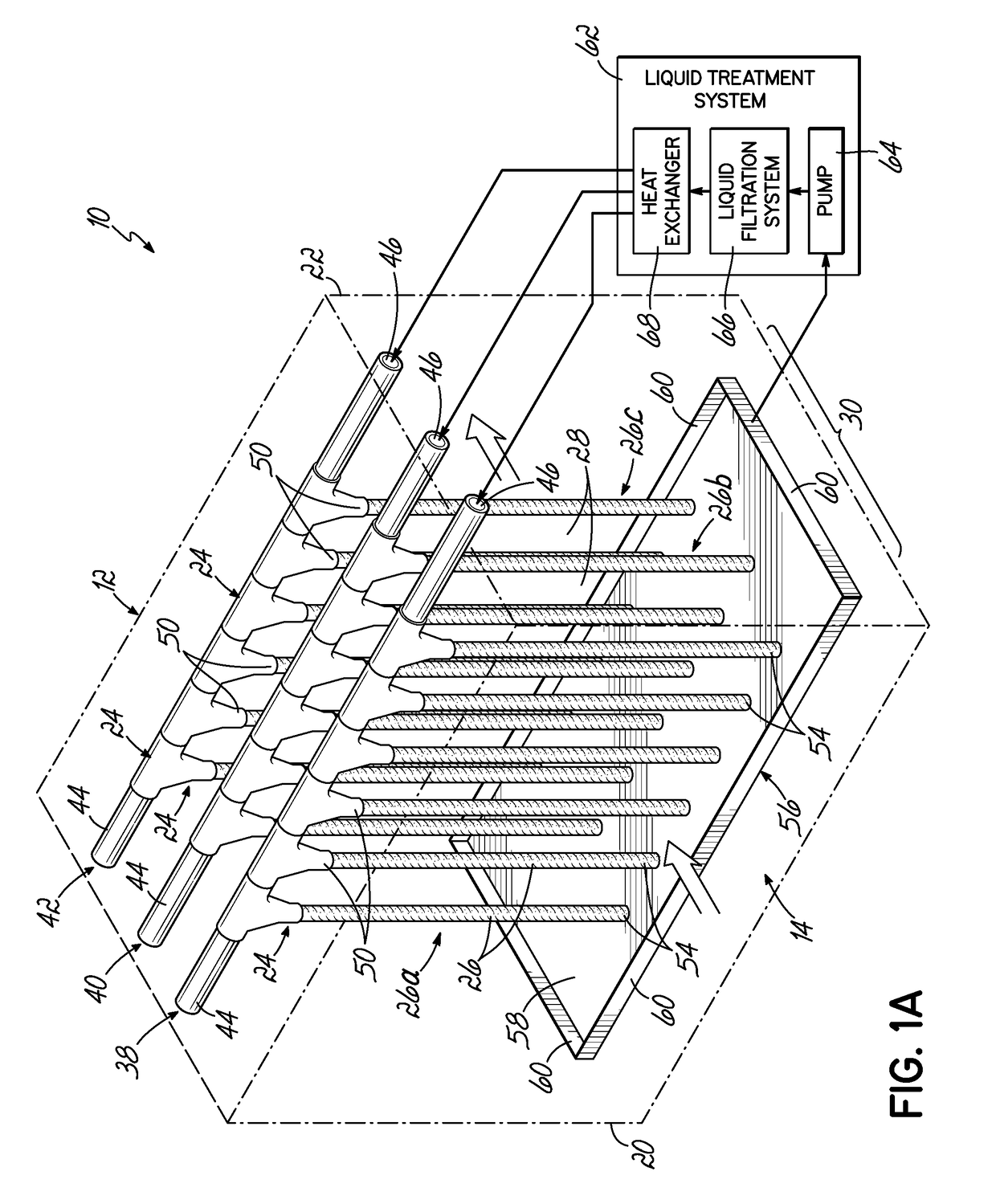
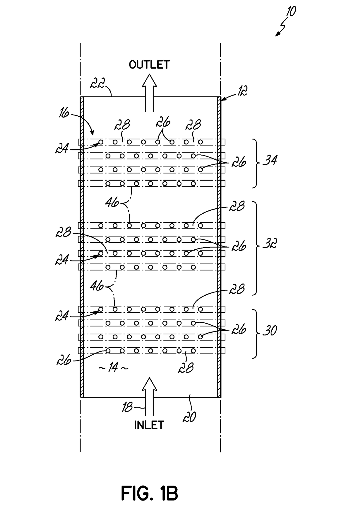
[0090]A bench-scale test unit consisting of a 12 foot long inlet, 4 foot outlet and 2 foot long test section between the two. The test section houses two or eight 1-inch thick sieves, set three inches apart. Each sieve consists of 30 polypropylene 5-mm ropes (actually it is a single rope, which is looped through holes) distanced 10 mm center to center, occupying 30×12-inch space with the total area of 360 square inches=0.23 square meters. Ropes in the neighboring sieves were aligned, not staggered,

[0091]In order to be able to apply variable tension force to the rope(s), on top a single rope is looped through holes in a thick hollow beam which could move up or down. Tension in the rope(s) was 25, 35 or 45 pounds.

[0092]PVC pipes were used to deliver water running down the strings. The amount of water used in all tests was 0.75 liters per minute per cell, in all cells.

[0093]The 3-micron fly ash with concentration ranging from 30 to 70 mg / m̂3 was injected into air at the inlet using SCH...


PUM

PropertyMeasurementUnit
Frequencyaaaaaaaaaa
Massaaaaaaaaaa
Massaaaaaaaaaa

Abstract

A vibrating wet precipitator is designed to remove particulates from particulate-laden hot gas. The precipitator includes an array of vertical wet cords stretched within a duct. The cords are tuned to vibrate due to the gas flow by controlling key parameters such as gas flow, velocity, cord length and diameter so that particulate collection and heat transfer efficiency are maximized. The cords are part of sieves. A plurality of these sieves are arranged to define a plurality of gaps, through which the exhaust flows. The sieves and thus the cords are space so that a vortex from a first cord affects an adjacent cord and subsequently cord. The particles are then absorbed in liquid, which can be passed through a heat exchanger filtered and subsequently reused. Preferably the cord arrangement is designed to allow the cords to vibrate at high frequencies, typically 10 to 100 Hz, to maximize particulate collection.

Description

TECHNICAL FIELD[0001]The present invention relates generally to a precipitator device and method of treating an exhaust, and more particularly, to a plurality of sieves for treating an exhaust.BACKGROUND[0002]Traditional precipitators, such as electrostatic precipitators, and scrubbers are widely used for treating exhaust containing gaseous pollutants and / or particulate emissions. For example, industrial processes, such as power and heat generation, may generate environmentally harmful particulate and gaseous emissions that may remain suspended in the air. These emissions often present health hazards when inhaled by humans and animals. Also, the particulate emissions tend to settle on equipment and buildings and may cause discoloration or even interfere with the proper function of the equipment. As such, it is important to remove these particulate emissions from the exhaust.[0003]The exhaust can be passed through a traditional heat exchanger for recovering thermal energy from the ex...

Claims


Application Information

Patent Timeline
IPC IPC(8): B01D47/02B01D46/00B03C3/16B03C3/41B03C3/45
CPCB01D47/028B01D46/0053B03C3/16B03C3/41B03C3/455B03C3/49B03C3/763B01D47/02B03C3/76
Inventor PASIC, HAJRUDINALAM, KHAIRUL
Owner OHIO UNIV
Why Eureka
Try Eureka