Method and system for exhaust gas recirculation and heat recovery

Active Publication Date: 2018-05-03
FORD GLOBAL TECH LLC
View PDF3 Cites 7 Cited by
  • Summary
  • Abstract
  • Description
  • Claims
  • Application Information

AI Technical Summary

Benefits of technology

[0002]Engines may be configured with an exhaust heat recovery system for recovering heat of exhaust gas generated at an internal combustion engine. The heat recovered at an exhaust gas heat exchanger may be utilized for functions such as heating the cylinder head, and warming the passenger cabin, thereby improving engine, and fuel efficiency. Cooled exhaust gas may be rec

Problems solved by technology

However, the inventors herein have recognized potential disadvantages with the above approach.
As one example, in the system shown by Ulrey et al., it may not be possible to restrict undesired exhaust flow though the EGR delivery passage and the bypass passage even when the exhaust throttle is in a fully open position.
During higher than threshold engine temperature and engine load conditions, since it may not be possible to completely bypass the heat exchanger, undesired flow of hot exhaust through the coolant system may adversely affect the functionality

Method used


Image

  • Method and system for exhaust gas recirculation and heat recovery
  • Method and system for exhaust gas recirculation and heat recovery
  • Method and system for exhaust gas recirculation and heat recovery

Examples


Example

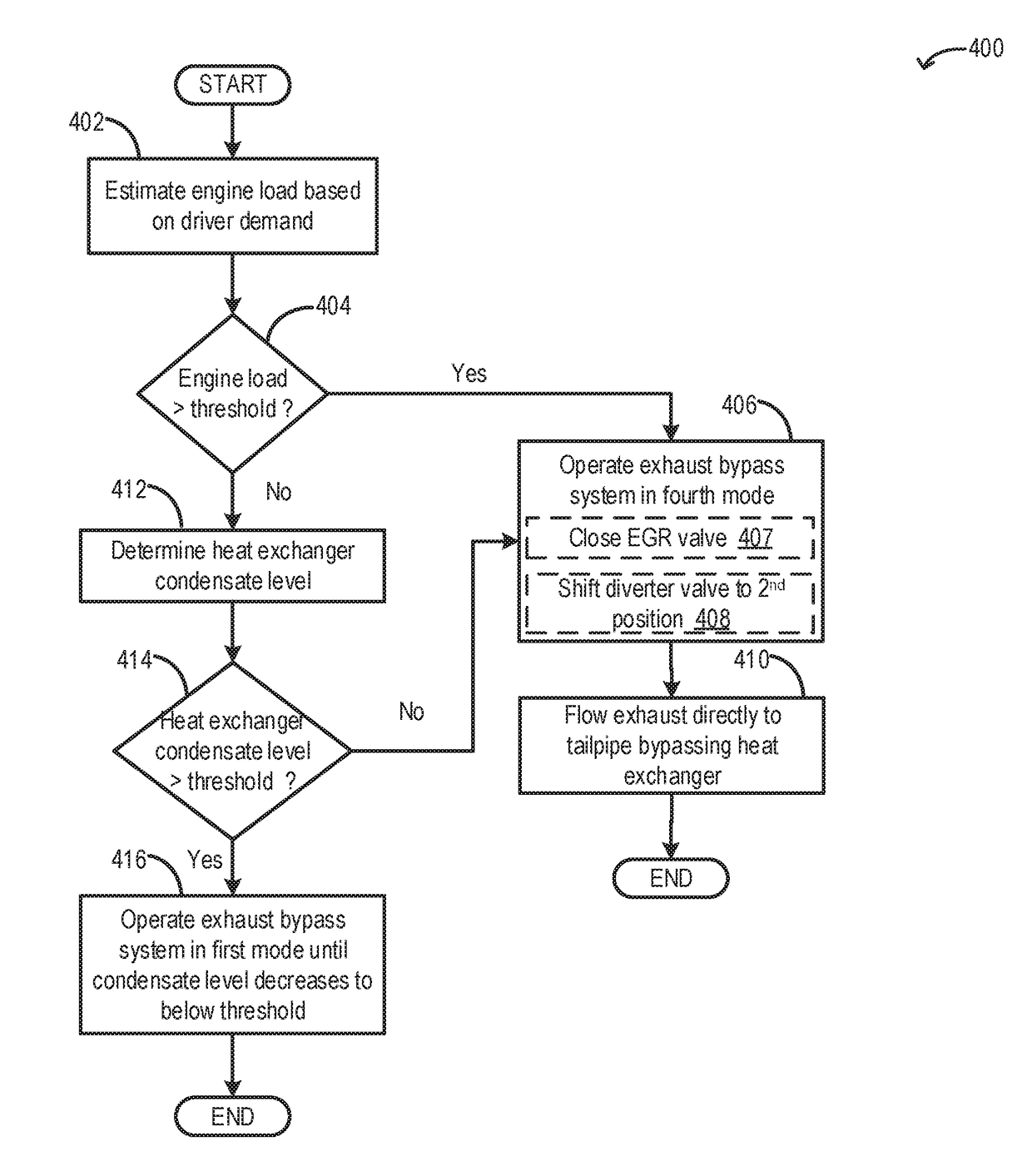
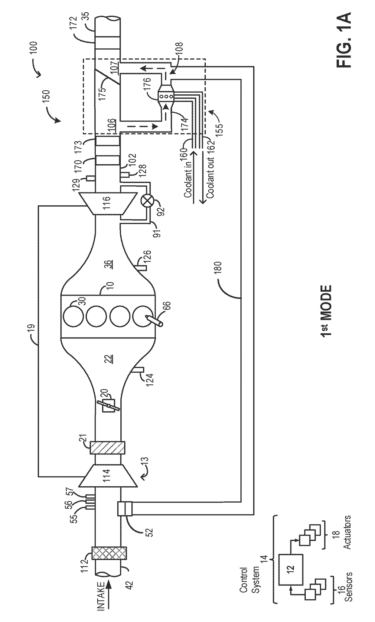
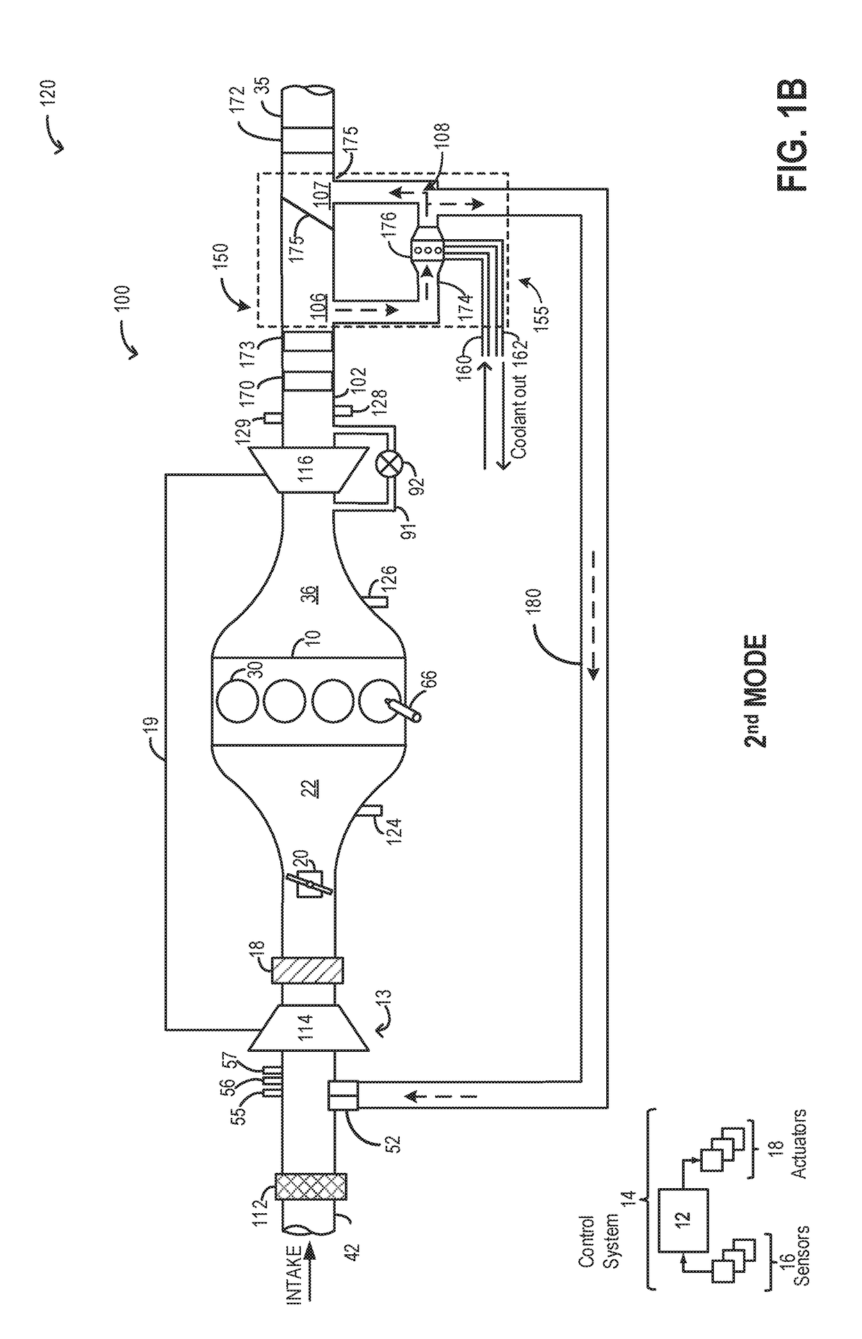
[0018]The following description relates to systems and methods for a single heat exchanger for improved exhaust gas heat recovery and exhaust gas recirculation (EGR) cooling. Different modes of operation of an example engine system comprising an engine exhaust system with a heat exchanger are shown in FIGS. 1A-1D. An example embodiment of a vehicle coolant system coupled to the engine system of FIGS. 1A-1D is shown in FIG. 2. An engine controller may be configured to perform a control routine, such as the example routines of FIGS. 3 and 4, to vary the positions of one or more exhaust system valves to adjust exhaust flow through the heat exchanger in the systems of FIGS. 1A-1D. The different modes of operation of the example engine system are tabulated in FIG. 5. An example operation of the systems of FIGS. 1A-1D is shown in FIG. 6.

[0019]FIG. 1A schematically shows aspects of an example engine system 100 including an engine 10. In the depicted embodiment, engine 10 is a boosted engin...


PUM


Abstract

Methods and systems are provided for exhaust heat recovery and EGR cooling via a single heat exchanger. In one example, a method may include selecting a specific mode of operation of an engine exhaust system with the heat exchanger based on engine operating conditions and an estimated fuel efficacy factor. The fuel efficiency factor may take into account fuel efficacy benefits from EGR and exhaust heat recovery.

Description

FIELD[0001]The present description relates generally to methods and systems for exhaust gas heat recovery and exhaust gas recirculation (EGR) cooling via a single heat exchanger.BACKGROUND / SUMMARY[0002]Engines may be configured with an exhaust heat recovery system for recovering heat of exhaust gas generated at an internal combustion engine. The heat recovered at an exhaust gas heat exchanger may be utilized for functions such as heating the cylinder head, and warming the passenger cabin, thereby improving engine, and fuel efficiency. Cooled exhaust gas may be recirculated to the intake manifold and used to reduce fuel consumption, and exhaust NOx emissions. Further, EGR may be used to assist in the reduction of throttling losses at low loads, and to improve knock tolerance. An EGR cooler may be coupled to an EGR delivery system to bring down the temperature of recirculated exhaust gas before it is delivered to the intake manifold.[0003]Various approaches are provided for exhaust he...

Claims


Application Information

Patent Timeline
IPC IPC(8): F02D41/00F01N3/10F02N19/10F02M26/33F02M26/15F02M26/14B60H1/04F01N5/02F01P3/20
CPCF02D41/005F01N3/10F02N19/10F02M26/33F01P2060/08F02M26/14B60H1/04F01N5/02F01P3/20F02M26/15F02M26/06F02M26/22F02D9/04F02D41/0077F02D2200/022F02D2041/1472F02D41/064F02D41/1446F02D41/1448F02D2200/021F02N2200/0804B60H1/025F02G5/04F01N3/0205F01P2060/16Y02T10/12Y02T10/40
Inventor SCHWARTZ, WILLIAM SAMUELMCCONVILLE, GREGORY PATRICKBAKER, CHAD ALLANBLATCHLEY, TIMOTHY NOAHUHRICH, MICHAEL JAMES
Owner FORD GLOBAL TECH LLC
Why Eureka
Try Eureka