Fuel Supply Device and Fuel Supply Method

a fuel supply device and fuel supply technology, applied in the direction of positive displacement liquid engines, piston pumps, machines/engines, etc., can solve the problems of large force needed by the reciprocating pump, difficult to independently control the individual reciprocating pumps, and inability to freely adjust the piston stroke, so as to suppress the occurrence of cavitation and prevent sudden decrease in the pressure inside the boosting cylinder.

Active Publication Date: 2018-05-03
MITSUI E&S MACHINERY CO LTD
View PDF0 Cites 2 Cited by
  • Summary
  • Abstract
  • Description
  • Claims
  • Application Information

AI Technical Summary

Benefits of technology

[0010]The present technology provides a fuel supply device and a fuel supply method capable of suppressing cavitation occurring in a reciprocating pump.
[0049]According to the present technology, it is possible to prevent sudden decrease in the pressure inside the boosting cylinder and to suppress the occurrence of cavitation.

Problems solved by technology

In a case where a piston of the reciprocating pump is driven using the crankshaft, since the piston stroke is determined by the crankshaft, it is not possible to freely adjust the piston stroke.
In addition, in a case where a plurality of reciprocating pumps is driven by an identical crankshaft, it is difficult to independently y control the individual reciprocating pumps.
On the other hand, the reciprocating pump needs a large force when ejecting fuel at a high pressure, while the load is small when sucking low pressure fuel.
For this reason, in a case where the reciprocating pump is driven using the hydraulic cylinder unit, the piston is more likely to move at a higher speed at suction when the load of the piston is small, and thus, the pressure inside the cylinder of the reciprocating pump occasionally becomes lower than the vapor pressure of the fuel, increasing the possibility of occurrence of cavitation.
The occurrence of cavitation leads to a problem of erosion occurring in the piston and cylinder of the reciprocating pump, causing shorter life.
Moreover, since the piston speed remains the same at ejection and at suction in a case where the reciprocating pump is driven using the crankshaft, it is difficult to change solely the speed at the time of suction, leading to the occurrence of cavitation at high rotation and high output.

Method used


Image

  • Fuel Supply Device and Fuel Supply Method
  • Fuel Supply Device and Fuel Supply Method
  • Fuel Supply Device and Fuel Supply Method

Examples


modification example

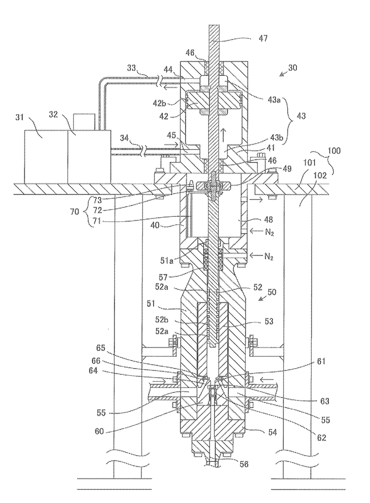
[0163]FIG. 6 is a diagram illustrating a fuel supply unit using an electric cylinder unit as the linear actuator 30. Note that the same reference numerals are given to the configurations similar to the configurations in FIGS. 2 and 3 and description thereof will be omitted.

[0164]The electric cylinder unit includes an electric motor 31, gears 35a and 35b, a ball nut 37, and a ball screw 38.

[0165]The gear 35a is rotated by the power of the electric motor 31, and the rotation of the gear 35a is transmitted to the gear 35b.

[0166]The gear 35bis provided integrally with the ball nut 37, and transmits the rotation of the gear 35a to the ball nut 37.

[0167]The ball nut 37 is screwed with the ball screw 38 and rotates together with the gear 35b.

[0168]The lower end of the ball screw 38 is coupled to the upper end of the boosting piston 52 via the coupling portion 49. Rotation of the ball nut 37 causes the ball screw 38 to move in the axial direction. Movement of the ball screw 38 in the axia...


PUM


Abstract

A fuel supply device includes: a linear actuator; a reciprocating pump having a boosting piston driven by the linear actuator, configured to axially reciprocate, and configured to alternately repeat suction of the fuel and ejection of the fuel more boosted than the fuel at a time of suction by reciprocation of the boosting piston; and a controller to control driving of the linear actuator. When reciprocation amplitude of the boosting piston is A (A>0) and a reciprocating cycle time is T, the controller controls the linear actuator so a maximum value of an absolute value of acceleration when the reciprocating pump sucks the fuel with an absolute value of speed of the boosting piston increasing is smaller than A·(2π / T)2, and so a maximum value of the absolute value of the acceleration of the boosting piston when the reciprocating pump ejects the fuel is larger than A·(2π / T)2.

Description

TECHNICAL FIELD[0001]The present technology relates to a fuel supply device and a fuel supply method for supplying fuel to an internal combustion engine such as a diesel engine.BACKGROUND ART[0002]In conventional ships, a two-stroke low speed diesel engine that can output at low speeds and can be driven in a state of being directly y connected to a propeller.[0003]In recent years, natural gas with low NOx and SOx emissions has received attention as fuel for low speed diesel engines. By injecting high pressure natural gas as fuel into a combustion chamber of a low speed diesel engine and burning it, an output can be obtained with high heat efficiency.[0004]In conventional ships, a two-stroke low speed diesel engine is used. The diesel engine can output at low speeds and is driven, directly y connected to a propeller.[0005]In recent years, natural gas with low NOx and SOx emissions has received attention as a fuel for low speed diesel engines. By injecting high pressure natural gas as...

Claims


Application Information

Patent Timeline
Patent Type & Authority Applications(United States)
IPC IPC(8): F02M59/26F02M37/08F02M37/12F04B49/06
CPCF02M59/26F04B49/06F02M37/12F02M37/08F02M57/023F04B9/042F02M59/02F02M39/02F02M37/06F02M59/20F02M2200/245F04B17/04F02M2200/241F02M59/105F02M21/0215F02M21/0245Y02T10/30F02M37/20
Inventor KOUNOSU, MAKOTOKITAMURA, SEIICHIKANDA, RENZO
Owner MITSUI E&S MACHINERY CO LTD
Why Eureka
Try Eureka