Continuous liquid interface production with upconversion photopolymerization

a technology of photopolymerization and liquid interface, which is applied in the direction of metal-working equipment, additive manufacturing, manufacturing tools, etc., can solve the problems of needing to submerge, extreme care, and use of additional mechanical elements

Active Publication Date: 2018-05-10
CARBON INC
View PDF0 Cites 190 Cited by
  • Summary
  • Abstract
  • Description
  • Claims
  • Application Information

AI Technical Summary

Problems solved by technology

A disadvantage of such “top down” techniques is the need to submerge the growing object in a (potentially deep) pool of liquid resin and reconstitute a precise overlayer of liquid resin.
While such “bottom up” techniques hold the potential to eliminate the need for a deep well in which the object is submerged by instead lifting the object out of a relatively shallow well or pool, a problem with such “bottom up” fabrication techniques, as commercially implemented, is that extreme care must be taken, and additional mechanical elements employed, when separating the solidified layer from the bottom plate due to physical and chemical interactions therebetween.
Such approaches introduce a mechanical step that may complicate the apparatus, slow the method, and / or potentially distort the end product.
This approach utilizes a window that is permeable to the inhibitor of polymerization, which in some embodiments may require the construction of a complicated or expensive window.
All pose difficulties for implementation in at least some circumstances, and additional alternatives are desirable.
Continuous processes for producing a three-dimensional object are suggested at some length with respect to “top down” techniques in U.S. Pat. No. 7,892,474, but this reference does not explain how they may be implemented in “bottom up” systems in a manner non-destructive to the article being produced, which limits the materials which can be used in the process, and in turn limits the structural properties of the objects so produced.

Method used


Image

  • Continuous liquid interface production with upconversion photopolymerization
  • Continuous liquid interface production with upconversion photopolymerization
  • Continuous liquid interface production with upconversion photopolymerization

Examples


first embodiment

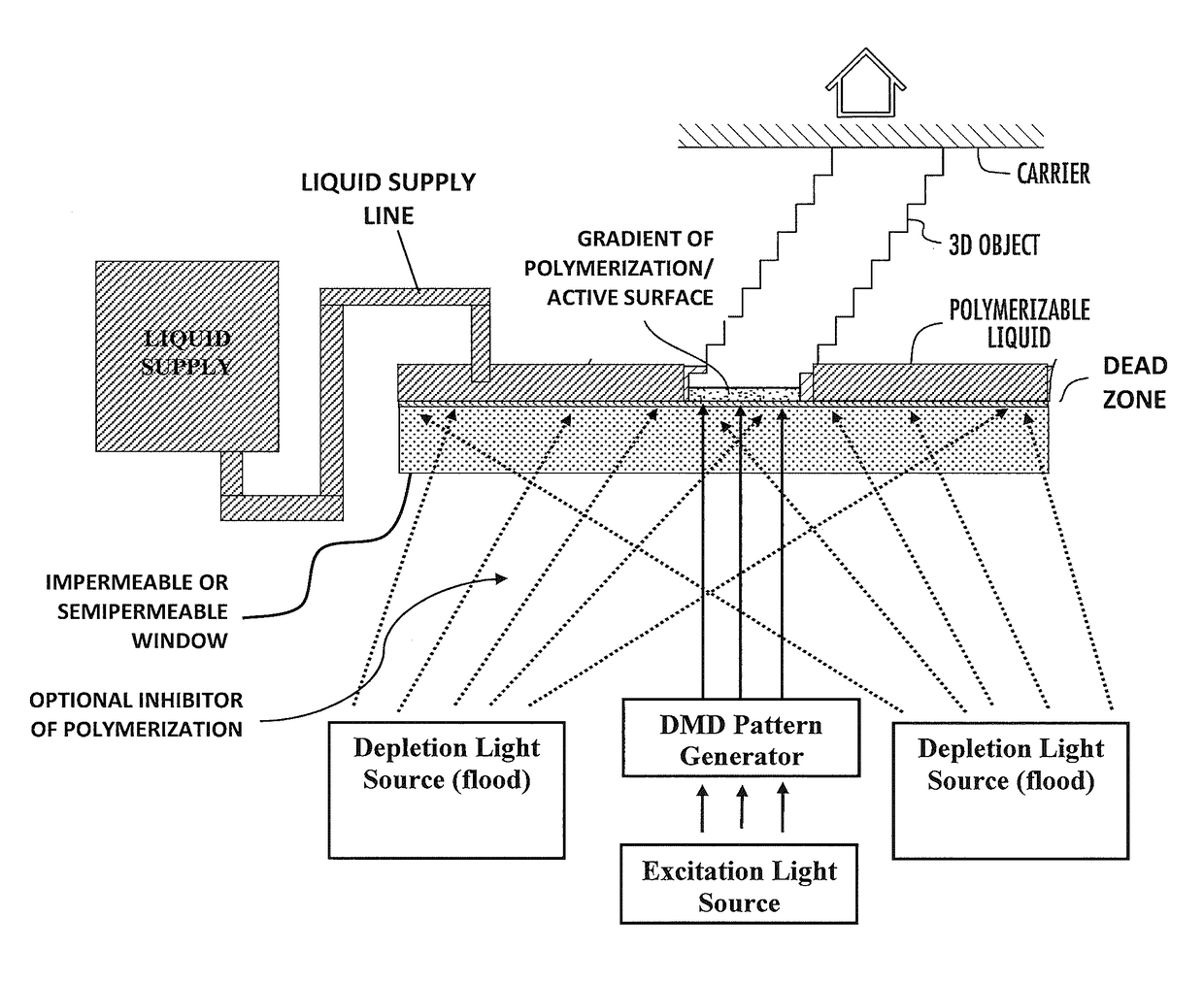
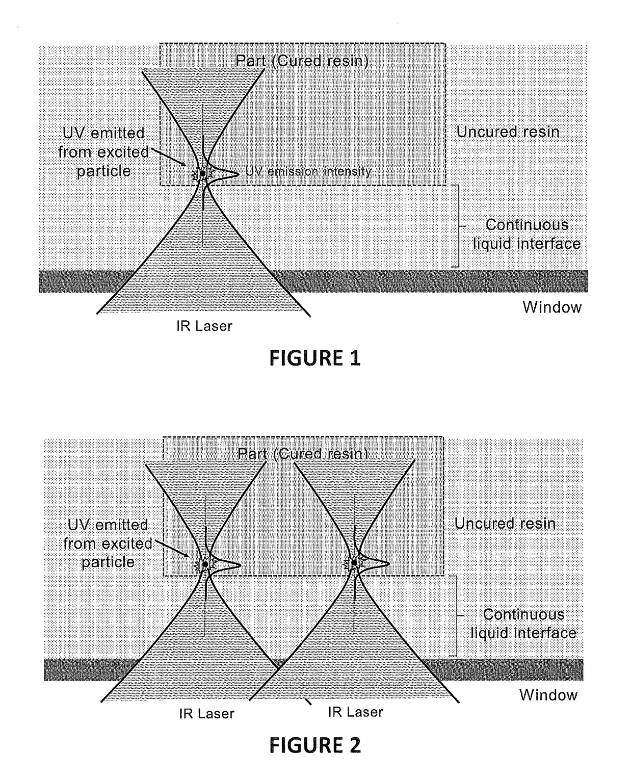
[0086]FIG. 1 illustrates a method of producing a three dimensional object, while maintaining a continuous liquid interface, the method utilizing upconversion particles (as described above) in the resin. In this embodiment, resin is held in a container above an optically transparent, gas impermeable (and specifically oxgen impermeable), window (e.g., glass or sapphire). The resin is irradiated with infrared light focused with a high numerical aperture to generate a high intensity focal spot with short depth of focus at a location away from the window in the resin (e.g., 10 or 20 to 100 or 200 or 1000 to 10000 um above the window). The cure rate of the resin is only appreciable near the focal spot, so curing occurs only near the focal spot and an uncured, liquid, resin layer is continuously maintained near the window, while the part is continuously or intermittently advanced away from the window to form the three-dimensional object. Concurrently or sequentially with the advancement of...

second embodiment

[0115]FIGS. 9A-9B schematically illustrate a dual wavelength scheme, in which, in which (i) the overall depletion intensity is relatively high, but is not uniform (is spatially modulated). Specifically, the center pixel receives low intensity depletion light (not shown), as in FIG. 8A, while the surrounding eight pixels receive higher intensity depletion light. There is some optical overlap between the pixels (e.g., achieved by slight defocusing). The polymerized size of the feature or segment of the object polymerized by the center pixel is smaller, due to the depletion beam spilling over into excitation beam, yet remains centered in the horizontal dimension of the object, relative to the pixels delivering light, because of the equal intensity of the depletion light delivered in the surrounding pixels.

third embodiment

[0116]FIGS. 10A-10B schematically illustrate a dual wavelength scheme, in which (i) the depletion intensity is both high and low (spatially modulated). Specifically, the center pixel, and the pixels on the right, receive low intensity depletion light, while the pixels to the left, and above and below the center pixel, receive higher intensity depletion light. Again there is some optical overlap between the pixels (e.g., achieved by slight defocusing). The polymerized size of the feature or segment of the object polymerized by the center pixel is smaller and shifted to the right, due to the depletion beam spilling over in an unequal or offset manner into the excitation beam.

[0117]While the dead zone and the gradient of polymerization zone do not have a strict boundary therebetween (in those locations where the two meet), the thickness of the gradient of polymerization zone is in some embodiments at least as great as the thickness of the dead zone. Thus, in some embodiments, the dead ...


PUM

PropertyMeasurementUnit
wavelengthaaaaaaaaaa

Abstract

A method of forming a three-dimensional object can be carried out by: (a) providing a carrier and an optically transparent member having a build surface, the carrier and the build surface defining a build region therebetween; (b) filling the build region with a polymerizable liquid, the polymerizable liquid comprising: (i) a polymerizable component; (ii) upconverting particles that are excited by light at a first wavelength and upon excitation emit light at a second wavelength that is shorter than the first wavelength; and (iii) a photoiniator that catalyzes polymerization of the polymerizable component upon excitation by light at the second wavelength; (c) irradiating the build region through the optically transparent member with an excitation light at the first wavelength, and optionally but in some embodiments preferably also advancing the carrier away from the build surface, wherein the excitation light is temporally and / or spatially modulated, to thereby form the three-dimensional object from the polymerizable liquid.

Description

RELATED APPLICATION[0001]This application claims priority to U.S. Provisional Patent No. 62 / 417,758, filed Nov. 4, 2017, the disclosure of which is hereby incorporated by reference in its entirety.FIELD OF THE INVENTION[0002]The present invention concerns materials, methods and apparatus for the fabrication of solid three-dimensional objects from liquid materials, and objects so produced.BACKGROUND OF THE INVENTION[0003]In conventional additive or three-dimensional fabrication techniques, construction of a three-dimensional object is performed in a step-wise or layer-by-layer manner. In particular, layer formation is performed through solidification of photo curable resin under the action of visible or UV light irradiation. Two techniques are known: one in which new layers are formed at the top surface of the growing object; the other in which new layers are formed at the bottom surface of the growing object.[0004]If new layers are formed at the top surface of the growing object, th...

Claims


Application Information

Patent Timeline
Patent Type & Authority Applications(United States)
IPC IPC(8): B29C64/135B29C64/277B33Y10/00B33Y70/00
CPCB29C64/135B29C64/277B33Y10/00B33Y70/00B29K2105/0094B29K2995/0021B29C64/124B29C64/129B33Y70/10
Inventor PANZER, MATTHEWTUMBLESTON, JOHN R.
Owner CARBON INC
Why Eureka
Try Eureka