Intelligent Pressure Management System for Cryogenic Fluid Systems

a technology of intelligent pressure management and cryogenic fluid, which is applied in the direction of gas/liquid distribution and storage, fuel supply apparatus, vessel construction details, etc., can solve the problems of reduced vapor pressure, high tank pressure of cryogenic fuel, and inefficient management of engine operation and fluid handling of cryogenic fuel, etc., and achieve the effect of high load requirement of the use devi

Active Publication Date: 2018-05-10
WESTPORT FUEL SYST CANADA INC
View PDF0 Cites 12 Cited by
  • Summary
  • Abstract
  • Description
  • Claims
  • Application Information

AI Technical Summary

Benefits of technology

[0012]In some exemplary systems, a controller operates in a predictive mode to adjust the preset pressure target based on at least one of a learned operator use pattern, learned system use pattern, user input, and a geographical location based input that could indicate for example imminent refueling (distance and / or time to refuel), imminent return to home base, imminent parking, imminent shut down, and imminent high load mode requirements. The preset pressure target may be lowered at a predetermined distance and / or time to at least one of system refueling, system return to home base, system parking, and system shut down. The preset pressure target may be raised at a predetermined distance and / or time to a high load requirement of the use device.

Problems solved by technology

Cryogenic fuel tanks typically have high tank pressure after filling up the tank at refueling or after sitting for multiple days without use.
However mechanical systems such as ones that employ an economizer valve have no way of reacting to varying use device demands; these systems are designed to blindly consume the vapor from the tank first only when the tank pressure has fallen below a set point, such systems will switch over to liquid fuel delivery.
However while this system takes into account engine demand it has been found that engine operation and fluid handling of the cryogenic fuel are still managed inefficiently by such systems because pressure set points are still fixed; for example, this results in vapor pressure being reduced at times when it would be advantageous to keep vapor pressure higher.

Method used


Image

  • Intelligent Pressure Management System for Cryogenic Fluid Systems
  • Intelligent Pressure Management System for Cryogenic Fluid Systems
  • Intelligent Pressure Management System for Cryogenic Fluid Systems

Examples


Embodiment Construction

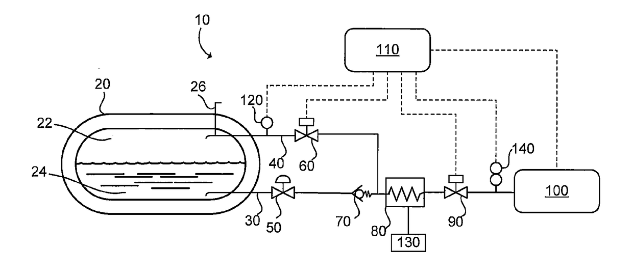
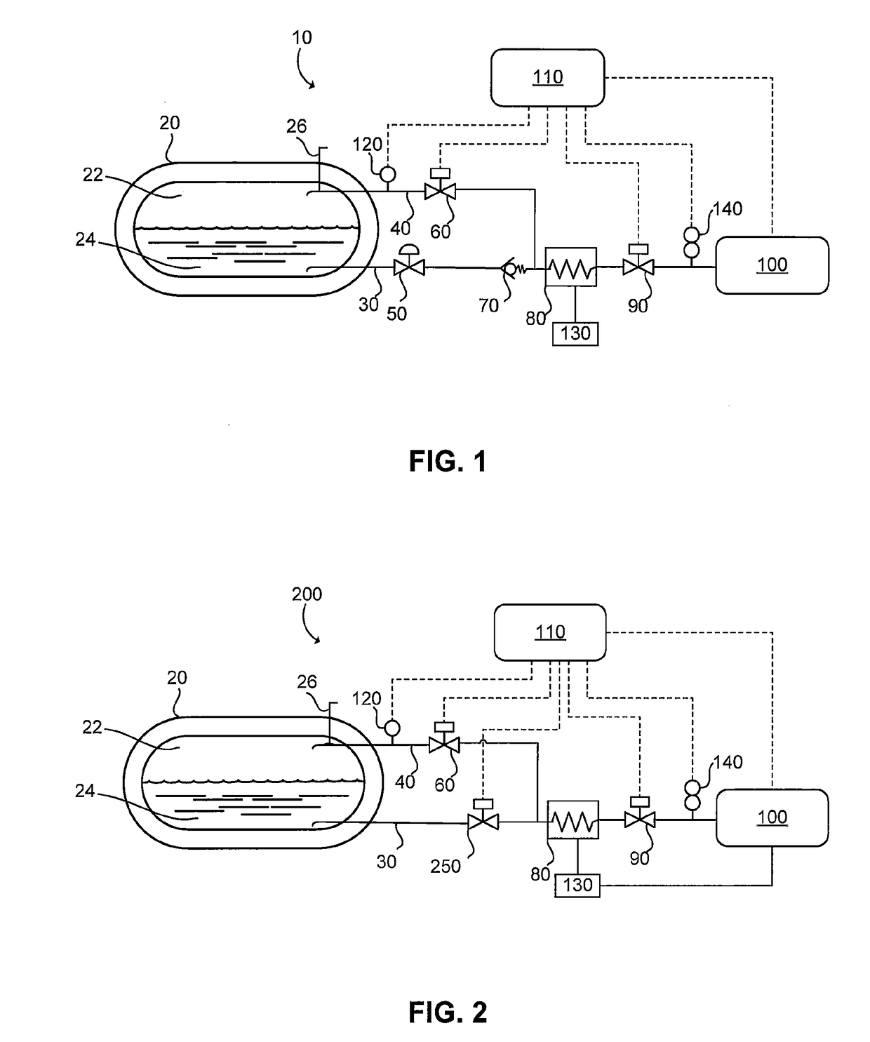
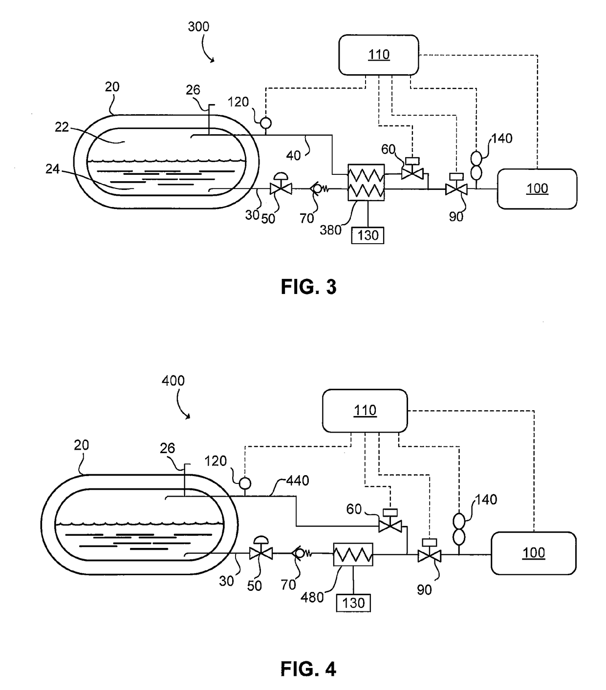
[0020]An intelligent pressure management system that controls the pressure inside a cryogenic tank between variable target vapor pressure values and / or ranges that are set as a function of system operating conditions is disclosed herein. The system is designed to actuate an actively controllable vapor valve disposed on a gaseous fluid vapor conduit (and in some exemplary systems, additionally actuate an actively controllable valve on a liquefied gaseous fluid conduit) based on a signal received from a pressure sensor that measures the pressure inside the pressurized tank. The variable target vapor pressure values and / or ranges are determined as a function of at least two system operating conditions which can include the vapor volume in the storage space; the fluid flow demanded by the use device; and a measured temperature parameter that correlates to the temperature of the fluid exiting a heater that heats the gaseous fluid before it is delivered to the use device. In one preferred...


PUM


Abstract

An intelligent pressure management system that controls the pressure inside a cryogenic tank between variable target vapor pressure values and/or ranges that are set as a function of system operating conditions, by actuating an actively controllable valve disposed on a gaseous fluid vapor conduit; and in some embodiments, additionally by actuating an actively controllable valve on a liquefied gaseous fluid conduit, based on a signal received from a pressure sensor that measures the pressure inside the pressurized tank. The variable target vapor pressure values and/or ranges are determined as a function of at least two system operating conditions which can include the vapor volume in the storage space; the fluid flow demanded by the use device; and a measured temperature parameter that correlates to the temperature of the fluid exiting a heater.

Description

FIELD OF THE INVENTION[0001]The present disclosure relates generally to an electronically controlled vapor pressure management system for gaseous fluid supply systems and more particularly to managing cryogenic fluid vapor pressure especially useful in supplying fluid to a use device such as an engine system operating at least in part using gaseous fuel.BACKGROUND OF THE INVENTION[0002]To reduce the storage volume, gaseous fluids can be stored in liquefied form at cryogenic temperatures when employed for example as fuel for internal combustion engines. A gaseous fluid including a gaseous fuel is defined as any fluid that is in a gas state at standard temperature and pressure which is defined herein as 1 atmosphere and between 20 and 25 degrees Celsius. Gaseous fuel is normally stored near its boiling point in a storage vessel. For example, for methane at a storage pressure of about 1 atmosphere it can be stored in liquefied form at a temperature of about −161 degrees Celsius. Natura...

Claims


Application Information

Patent Timeline
Patent Type & Authority Applications(United States)
IPC IPC(8): F02M21/02F02M21/06F17C13/02F17C9/02
CPCF02M21/0215F02M21/06F17C13/025F17C9/02F17C2201/035F17C2205/0326F17C2205/0332F17C2205/0335F17C2221/033F17C2223/0161F17C2223/033F17C2223/043F17C2223/046F17C2225/0123F17C2227/0323F17C2227/0393F17C2250/032F17C2250/043F17C2250/0439F17C2260/021F17C2265/066F17C2270/0168F17C7/04F02M21/0221F02M21/0239F02M21/0212F17C2201/056Y02T10/30F17C2227/0316
Inventor GARNER, GAGE D.
Owner WESTPORT FUEL SYST CANADA INC
Why Eureka
Try Eureka