Materials and methods for producing metal nanocomposites, and metal nanocomposites obtained therefrom

a technology of metal nanocomposites and metal nanocomposites, which is applied in the field of metal nanocomposites, can solve the problems of high capital investment of equipment for material processing, difficult to make metal nanocomposites, and high processing costs

Active Publication Date: 2018-05-17
HRL LAB
View PDF8 Cites 30 Cited by
  • Summary
  • Abstract
  • Description
  • Claims
  • Application Information

AI Technical Summary

Benefits of technology

[0056]Step (b) may further include pressing, sintering, mixing, dispersing, friction stir welding, extrusion, binding, capacitive discharge sintering, casting, or a combination thereof. Step (b) may include holding the melt for an effective dwell time (e.g., abou...

Problems solved by technology

Currently, there are difficulties in making metal matrix nanocomposites including processing costs and high capital investment for equipment to process materials.
There are very few effective methods of maintaining a homogenously dispersed nanoparticle reinforcement phase in a metal matrix, especially in melt processing.
Reinforcement phase reactivity and particulate agglomeration of nanoscale reinforcement limit the strengthening effects in currently produced metal matrix nanocomposites.
Current methods for producing low-volume-fraction nanocomposites are limited to in-situ reaction mechanisms in highly specific alloy systems.
The materials are therefore extremely expensive and geometry-limited.
Thus the material cannot be made with uniform properties through the thickness.
High volume loading of nanoscale reinforcements ex situ is limited to few processes and none with the capability of producing geometrically complex shapes and at a low cost.
Current melt processing methods such as shear mixing or ultrasonic processing of metal matrix nanocomposites suffer from a limited availability of compatible materials due to reactivity and dispersion issues.
These methods are capable of dispersing low volume percentages of certain reinforcement phases; however, complications arise at higher reinforcement volume loading percentages as the effects of dispersion become more localized and less effective at higher melt viscosities.
Also, very large high-energy ball mills present both cost and safety barriers.
Nanomaterials may also be incorporated in the melt, but distribution of the nanomaterials can be difficult due to the surface energies associated with liquid metal.
Ultrasonic mixing or high-shear mixing can be effective, but they are size-limited and require manipulation of molten metal, which again presents cost and safety barriers.
Functionally graded metal matrix nanocomposites have not yet been successfully ...

Method used


Image

  • Materials and methods for producing metal nanocomposites, and metal nanocomposites obtained therefrom
  • Materials and methods for producing metal nanocomposites, and metal nanocomposites obtained therefrom
  • Materials and methods for producing metal nanocomposites, and metal nanocomposites obtained therefrom

Examples


example 1

n of AlSi10Mg—WC Functionally Graded Metal Matrix Nanocomposite

[0305]In this example, a functionally graded metal matrix nanocomposite is produced, with AlSi10Mg alloy and tungsten carbide (WC) nanoparticles. The starting AlSi10Mg alloy has an approximate composition of 10 wt % silicon (Si), 0.2-0.45 wt % magnesium (Mg), and the remainder aluminum (Al) except for impurities (e.g., Fe and Mn). The density of tungsten carbide 15.6 g / cm3 and the density of AlSi10Mg is 2.7 g / cm3. The tungsten carbide nanoparticles have a typical particle size of 15 nm to 250 nm.

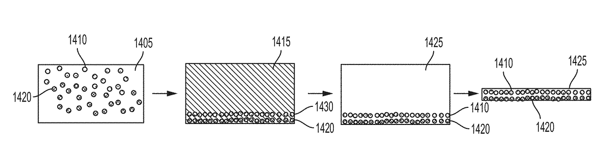
[0306]Tungsten carbide nanoparticles are assembled on an AlSi10Mg alloy powder. This material is consolidated under 300 MPa compaction force and then melted in an induction heater at 700° C. for one hour. The resulting material (FIG. 10) exhibits a functional gradient according to the distribution of WC nanoparticles. FIG. 10 is an SEM image of a cross-section (side view) of the resulting AlSi10Mg—WC functionally graded metal mat...

example 2

n of AlSi10Mg—WC Master Alloy Metal Matrix Nanocomposite

[0308]In this example, a master alloy metal matrix nanocomposite is produced, with AlSi10Mg alloy and tungsten carbide (WC) nanoparticles.

[0309]A functionally graded metal matrix nanocomposite is first produced according to Example 1. The material shown in FIG. 10 is the precursor to the master alloy. According to FIG. 10, the tungsten carbide nanoparticles are preferentially located (functionally graded) toward the bottom of the structure. This is also analogous to the schematic of FIG. 6. The AlSi10Mg alloy (metal matrix phase) toward the top contains little or no tungsten carbide nanoparticles. The desired material for this master alloy is the lower phase, containing a higher volume of tungsten carbide nanoparticles distributed within the AlSi10Mg phase.

[0310]The AlSi10Mg alloy (metal matrix phase) labeled “AlSi” is then separated from the lower phase labeled “AlSi+WC”. The resulting material is a master alloy metal matrix n...


PUM

PropertyMeasurementUnit
Sizeaaaaaaaaaa
Sizeaaaaaaaaaa
Sizeaaaaaaaaaa

Abstract

Some variations provide a metal matrix nanocomposite composition comprising metal-containing microparticles and nanoparticles, wherein the nanoparticles are chemically and/or physically disposed on surfaces of the microparticles, and wherein the nanoparticles are consolidated in a three-dimensional architecture throughout the composition. The composition may serve as an ingot for producing a metal matrix nanocomposite. Other variations provide a functionally graded metal matrix nanocomposite comprising a metal-matrix phase and a reinforcement phase containing nanoparticles, wherein the nanocomposite contains a gradient in concentration of the nanoparticles. This nanocomposite may be or be converted into a master alloy. Other variations provide methods of making a metal matrix nanocomposite, methods of making a functionally graded metal matrix nanocomposite, and methods of making a master alloy metal matrix nanocomposite. The metal matrix nanocomposite may have a cast microstructure. The methods disclosed enable various loadings of nanoparticles in metal matrix nanocomposites with a wide variety of compositions.

Description

PRIORITY DATA[0001]This patent application is a non-provisional application with priority to U.S. Provisional Patent App. No. 62 / 422,925, filed on Nov. 16, 2016; U.S. Provisional Patent App. No. 62 / 422,930, filed on Nov. 16, 2016; and U.S. Provisional Patent App. No. 62 / 422,940, filed on Nov. 16, 2016, each of which is hereby incorporated by reference herein.FIELD OF THE INVENTION[0002]The present invention generally relates to metal matrix nanocomposites, and methods of making and using the same.BACKGROUND OF THE INVENTION[0003]Metal matrix nanocomposite materials have attracted considerable attention due to their ability to offer unusual combinations of stiffness, strength to weight ratio, high-temperature performance, and hardness. There is a wide variety of commercial uses of metal matrix nanocomposites, including high-wear-resistant alloy systems, creep-resistant alloys, high-temperature alloys with improved mechanical properties, and radiation-tolerant alloys.[0004]Currently, ...

Claims


Application Information

Patent Timeline
IPC IPC(8): B22D23/06B22F1/00C22C21/02C22C1/05B22F1/17B22F1/18
CPCB22D23/06B22F1/0044C22C21/02C22C1/05B22F2301/052B22F2302/10C22C1/1036C22C32/00C22C32/0052B22F2998/10B22F2999/00B22F7/04B22F2007/045B22F1/17B22F1/18B22F2207/01B22D23/00Y10T428/12021B22F1/054B22F1/16C22C1/0416
Inventor MARTIN, JOHN H.YAHATA, BRENNAN D.
Owner HRL LAB
Why Eureka
Try Eureka