Tip Extensions for Wind Turbine Rotor Blades and Methods of Installing Same

a technology of wind turbines and rotor blades, which is applied in the field of wind turbine rotor blades, can solve the problems of significant dwell time for curing attachment adhesives, high cost and time-consuming installation techniques and systems of attaching conventional add-on components, and achieve the effect of enhancing the structural of the rotor blad

Active Publication Date: 2018-05-17
GENERAL ELECTRIC CO
View PDF4 Cites 26 Cited by
  • Summary
  • Abstract
  • Description
  • Claims
  • Application Information

AI Technical Summary

Benefits of technology

[0021]In additional embodiments, as mentioned, the tip extension may include one or more internal structural components, including, for example, a transition area structural support and/or an internal structural channel. As such, the tip end of the rotor blade may be configured to fit within the transition area structural support, whereas the conductive extension may be configured to fit within the internal structural channel. Such internal structural components are configured to provide enhanced structural to the rotor blade.
[0022]In further embodiments, the rotor blade assembly may also include an adhesive and/or one or more strips of a double-sided adhesive tape configured for securing the tip extension

Problems solved by technology

The installation techniques and systems for attaching conventional add-on components can be expensive and time consuming, particularly for field installations.
For example, typical field installation techniques require the use of attachment fixtures and significant dwell time for curing the attachment adhesives.
Such processes can be time consuming, expensive, and may damage the main blade structure.
Moreover, such processes may compromise the structural integrity and/or durability of the rotor blade, as well as its aerodynamic perform

Method used


Image

  • Tip Extensions for Wind Turbine Rotor Blades and Methods of Installing Same
  • Tip Extensions for Wind Turbine Rotor Blades and Methods of Installing Same
  • Tip Extensions for Wind Turbine Rotor Blades and Methods of Installing Same

Examples


Embodiment Construction

[0059]Reference now will be made in detail to embodiments of the invention, one or more examples of which are illustrated in the drawings. Each example is provided by way of explanation of the invention, not limitation of the invention. In fact, it will be apparent to those skilled in the art that various modifications and variations can be made in the present invention without departing from the scope or spirit of the invention. For instance, features illustrated or described as part of one embodiment can be used with another embodiment to yield a still further embodiment. Thus, it is intended that the present invention covers such modifications and variations as come within the scope of the appended claims and their equivalents.

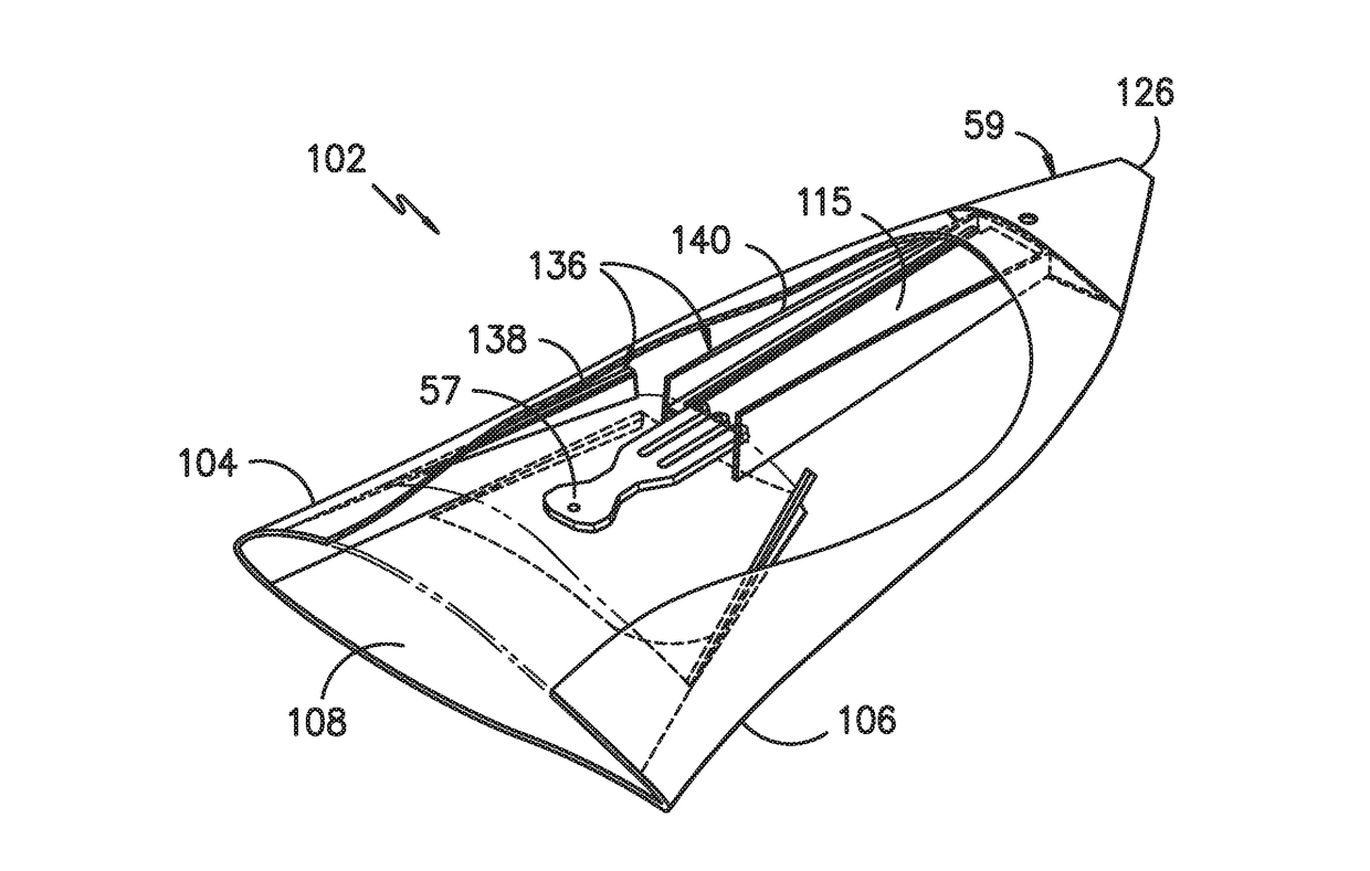
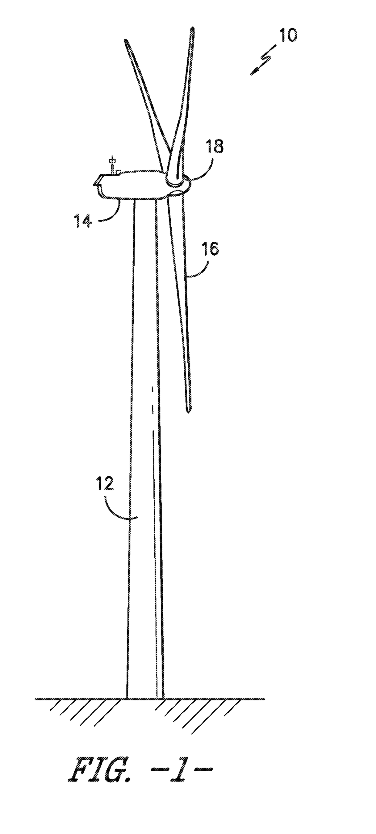
[0060]Referring now to the drawings, FIG. 1 illustrates a wind turbine 10 of conventional construction. As shown, the wind turbine 10 includes a tower 12 with a nacelle 14 mounted thereon. A plurality of blades 16 are mounted to a rotor hub 18, which is in ...


PUM


Abstract

The present disclosure is directed to tip extensions for wind turbine rotor blades and methods of installing same. The method includes removing a removable blade tip of a lightning protection system from the rotor blade so as to expose a down conductor of the lightning protection system. The method also includes securing a conductive extension to the down conductor. Moreover, the method includes sliding the first end of the tip extension over the conductive extension so as to overlap the rotor blade at the tip end. In addition, the method includes securing the removable blade tip to the conductive extension at the second end of the tip extension. Further, the method includes securing the tip extension to the rotor blade.

Description

FIELD OF THE INVENTION[0001]The present disclosure relates in general to wind turbine rotor blades, and more particularly to tip extensions for wind turbine rotor blades that tie into existing lightning protection systems thereof and methods of installing same.BACKGROUND OF THE INVENTION[0002]Wind power is considered one of the cleanest, most environmentally friendly energy sources presently available, and wind turbines have gained increased attention in this regard. A modern wind turbine typically includes a tower, a generator, a gearbox, a nacelle, and one or more rotor blades. The rotor blades capture kinetic energy of wind using known foil principles. The rotor blades transmit the kinetic energy in the form of rotational energy so as to turn a shaft coupling the rotor blades to a gearbox, or if a gearbox is not used, directly to the generator. The generator then converts the mechanical energy to electrical energy that may be deployed to a utility grid.[0003]In many cases, access...

Claims


Application Information

Patent Timeline
IPC IPC(8): F03D80/30F03D1/06
CPCF03D80/30F05B2230/23F05B2230/80F03D1/0675F05B2250/183Y02E10/72Y02P70/50F05B2240/307
Inventor TOBIN, JAMES ROBERTHARDISON, RICHARDLIVINGSTON, JAMIE T.
Owner GENERAL ELECTRIC CO
Why Eureka
Try Eureka