Eureka AIR delivers breakthrough ideas for toughest innovation challenges, trusted by R&D personnel around the world.

Sleeve monopole antenna with spatially variable dielectric loading

a dielectric loading and antenna technology, applied in the field of antennas, can solve the problems of difficult to achieve satisfactory antenna performance, limited antenna size, and compromised antenna mounting locations, and achieve the effect of less energy reflected, good impedance match, and increased energy

Active Publication Date: 2018-05-17
AMPHENOL ANTENNA SOLUTIONS
View PDF5 Cites 10 Cited by
  • Summary
  • Abstract
  • Description
  • Claims
  • Application Information

AI Technical Summary

Benefits of technology

The present invention is a new design for a special antenna that overcomes difficulties with traditional distributed antennas systems. The antenna has a sleeve and a limited size ground plane that work together to create a good impedance match in challenging environments. This means that less energy is reflected from the antenna and more is allowed to radiate, resulting in improved system efficiency and less power requirements. The antenna is also well-suited for DAS networks where omnidirectional radiation is desired. The sleeve monopole antenna provides some immunity to its operational environment due to its unique design and the use of a dielectric material between the sleeve and the primary radiating element to enhance control of the input impedance. The effective dielectric constant of the material allows the sleeve to function similar to a broadband impedance transformer enabling acceptable impedance matching over frequency.

Problems solved by technology

This is generally due to structures in the coverage area that would impede the wireless signal generated by the antenna at the access point from reaching all users within the coverage area.
Nearby objects can cause difficulties in impedance matching making it necessary to consider the operating environment in the antenna design.
This can be challenging for DAS networks where the antenna mounting locations are compromised due to physical space limitations or city and government regulations.
The resulting mounting locations can place antennas in close proximity to support structures or other infrastructure that can make it difficult to achieve satisfactory antenna performance.
Furthermore, antenna size can be limited where the antenna is constrained to fit within a given volume, and limitations in the ability to impedance match the antenna may result.
Outdoor DAS networks may present additional challenges where inclement weather can create dynamic operating environments.
This becomes a challenge when the concrete is exposed to water, i.e. rain or snow, as the concrete absorbs water due to its porosity.
As a result, the dielectric properties of the concrete can be impacted which can, in turn, impact the loading effects on a nearby antenna.
Broadband DAS networks are also challenging due to the need to maintain antenna performance over a broad frequency range.
Objects that may not have a significant impact to the antenna at higher frequencies may become problematic at lower frequencies.
As a result of the mounting location and size limitations, the low band antennas in the '801 application suffer from the difficulties in impedance matching and warrant a broadband impedance matching solution.
Those antennas are costly to fabricate and complicated to assemble.

Method used


Image

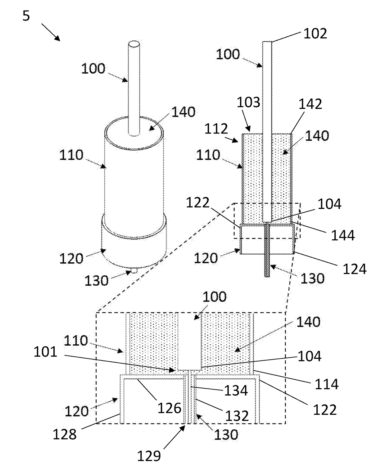
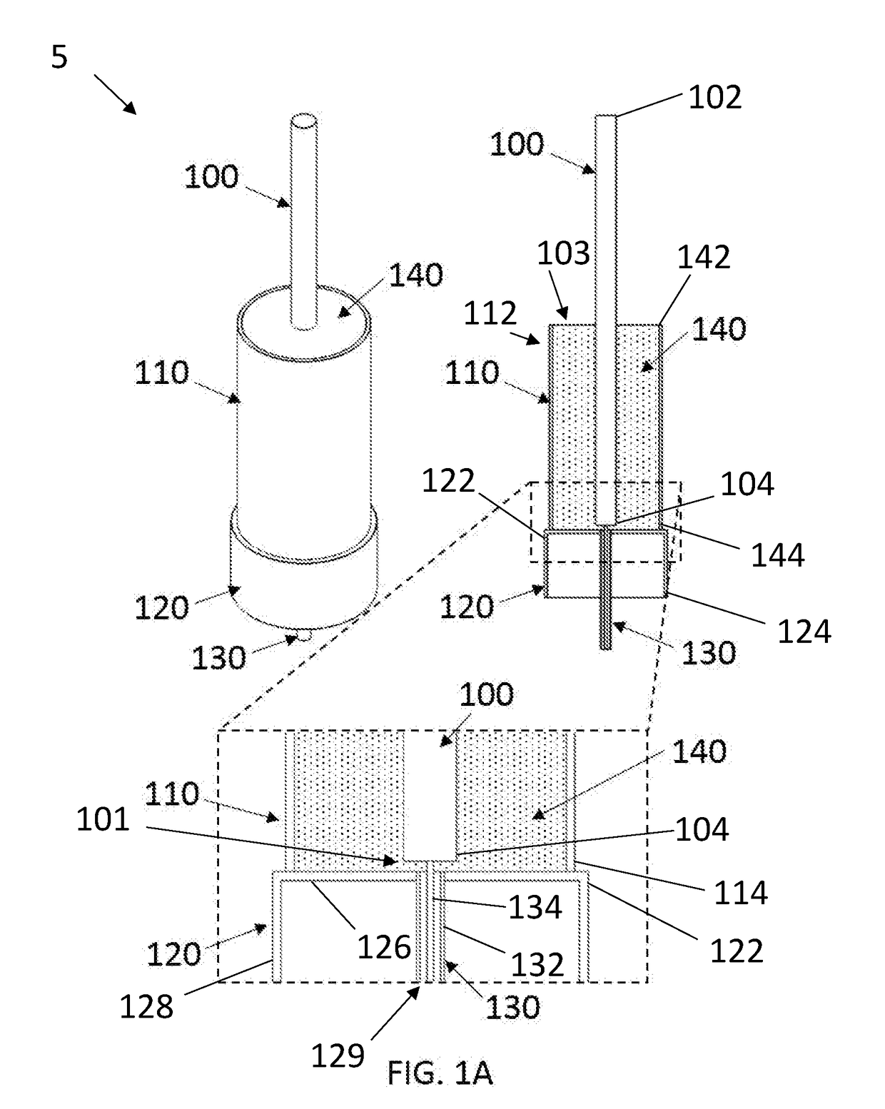
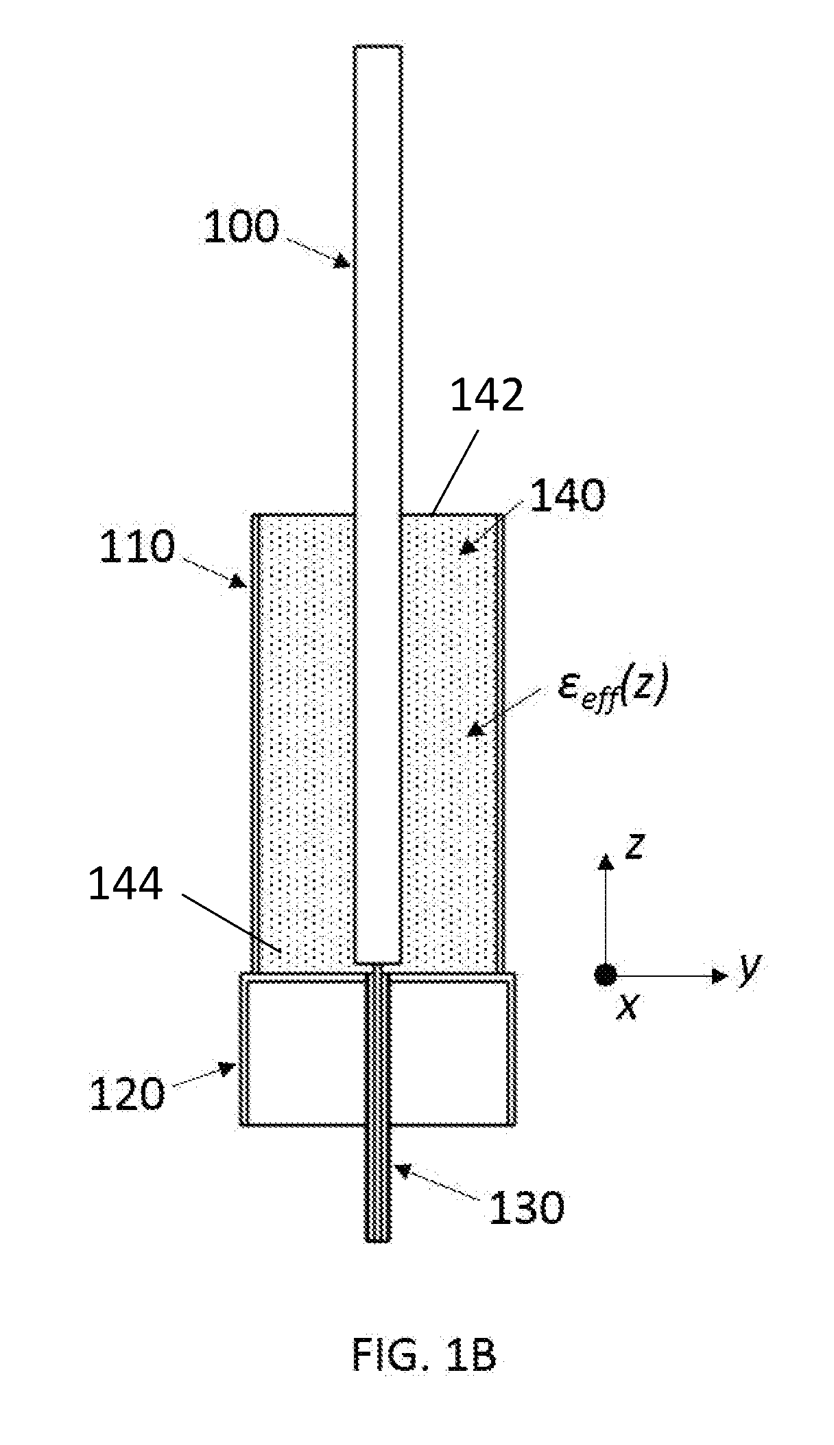
  • Sleeve monopole antenna with spatially variable dielectric loading
  • Sleeve monopole antenna with spatially variable dielectric loading
  • Sleeve monopole antenna with spatially variable dielectric loading

Examples


Embodiment Construction

[0017]In describing a preferred embodiment of the invention illustrated in the drawings, specific terminology will be resorted to for the sake of clarity. However, the invention is not intended to be limited to the specific terms so selected, and it is to be understood that each specific term includes all technical equivalents that operate in similar manner to accomplish a similar purpose. Several preferred embodiments of the invention are described for illustrative purposes; it being understood that the invention may be embodied in other forms not specifically shown in the drawings.

[0018]The present invention details a dielectric loaded sleeve monopole exhibiting broadband operation in challenging operational environments. The sleeve monopole is an uncomplicated yet robust antenna that can be configured to operate over broad bandwidths. For purposes of the present invention, an antenna exhibiting a −10 dB return loss over a 25% or greater fractional bandwidth is considered to be br...


PUM


Abstract

A dielectric loaded sleeve monopole antenna has a dielectric loading within the sleeve enables stable impedance in a dynamic operating environment. The use of a dielectric filling in the sleeve portion of the antenna enables tight control of the input impedance over frequency establishing stable broadband operation in challenging operating environments. The effective dielectric constant inside the sleeve of the antenna is designed to exhibit spatial variability. As a result, the sleeve essentially acts as an impedance transformer enhancing control over the input impedance to the antenna. The spatial variability in the dielectric filling may be realized as arrangements of single or multiple dielectric materials machined to synthesize the desired effective dielectric properties.

Description

BACKGROUND OF THE INVENTIONField of the Invention[0001]The present invention generally relates to antennas, and more specifically to the sleeve monopole antenna with dielectric loading.Background of the Related Art[0002]Distributed antenna systems (DAS) include a plurality of antennas distributed throughout a particular coverage area. DAS solutions are generally deployed to provide wireless coverage in areas that cannot be covered by a single access point. This is generally due to structures in the coverage area that would impede the wireless signal generated by the antenna at the access point from reaching all users within the coverage area. Some examples include office buildings, university campuses, and stadiums.[0003]An antenna is generally impacted by objects in close proximity to the antenna especially when the object falls within the antenna's near field. Nearby objects can cause difficulties in impedance matching making it necessary to consider the operating environment in t...

Claims


Application Information

Patent Timeline
Patent Type & Authority Applications(United States)
IPC IPC(8): H01Q13/24H01Q1/48H01Q1/24
CPCH01Q13/24H01Q1/24H01Q1/48H01Q9/32H01Q5/50H01Q9/22H01Q9/30H01Q13/06
Inventor SHEHAN, JOSHUA W.
Owner AMPHENOL ANTENNA SOLUTIONS
Why Eureka
Eureka Blog
Learn More