Control method and system for protection of wind turbines

a technology of control method and wind turbine protection, which is applied in the direction of wind turbines, engine components, wind energy generation, etc., can solve the problems of increasing insulation breakdown rate, increasing the accumulation rate of fatigue damage, so as to reduce the amount of power, or even completely cancel the effect of winding temperature reduction

Active Publication Date: 2018-06-07
VESTAS WIND SYST AS
View PDF1 Cites 16 Cited by
  • Summary
  • Abstract
  • Description
  • Claims
  • Application Information

AI Technical Summary

Benefits of technology

[0006]The rated power of a wind turbine is defined in IEC 61400 as the maximum continuous electrical power output that a wind turbine is designed to achieve under normal operating and external conditions. Large commercial wind turbines are generally designed for a lifetime of 20 to 25 years and are designed to limit power output to the rated power level so that component loading is not excessive in high winds and the design loads and fatigue life of components are not exceeded.
[0031]The above method and control strategy may be employed to identify operation in unusually high turbulence conditions. Such high turbulence conditions may be caused by wind coming from a complex terrain direction, operation within a wake and / or operation in a thunderstorm. Over-rating can then be reduced, on a per-turbine basis, thereby reducing rate of accumulation of fatigue damage in mechanical components that are sensitive to turbulence and / or incur fatigue as function of power. The control strategy may alternatively, or in addition, identify operation at unusually high local temperatures in electrical components to also allow over-rating to be reduced, thereby reducing the rate of accumulation of fatigue (insulation) damage in electrical components for which fatigue is a function of power. For electrical components this applies particularly to those with short thermal time constants of less than approximately 1 h-3 h.

Problems solved by technology

For some mechanical components, operation in very high turbulence causes a rate of accumulation of fatigue damage that is many times higher than in normal turbulence.
For some electrical components, operation at very high temperatures causes a rate of accumulation of fatigue damage (such as insulation breakdown rate) that is many times higher than at normal temperatures.

Method used


Image

  • Control method and system for protection of wind turbines
  • Control method and system for protection of wind turbines
  • Control method and system for protection of wind turbines

Examples


Embodiment Construction

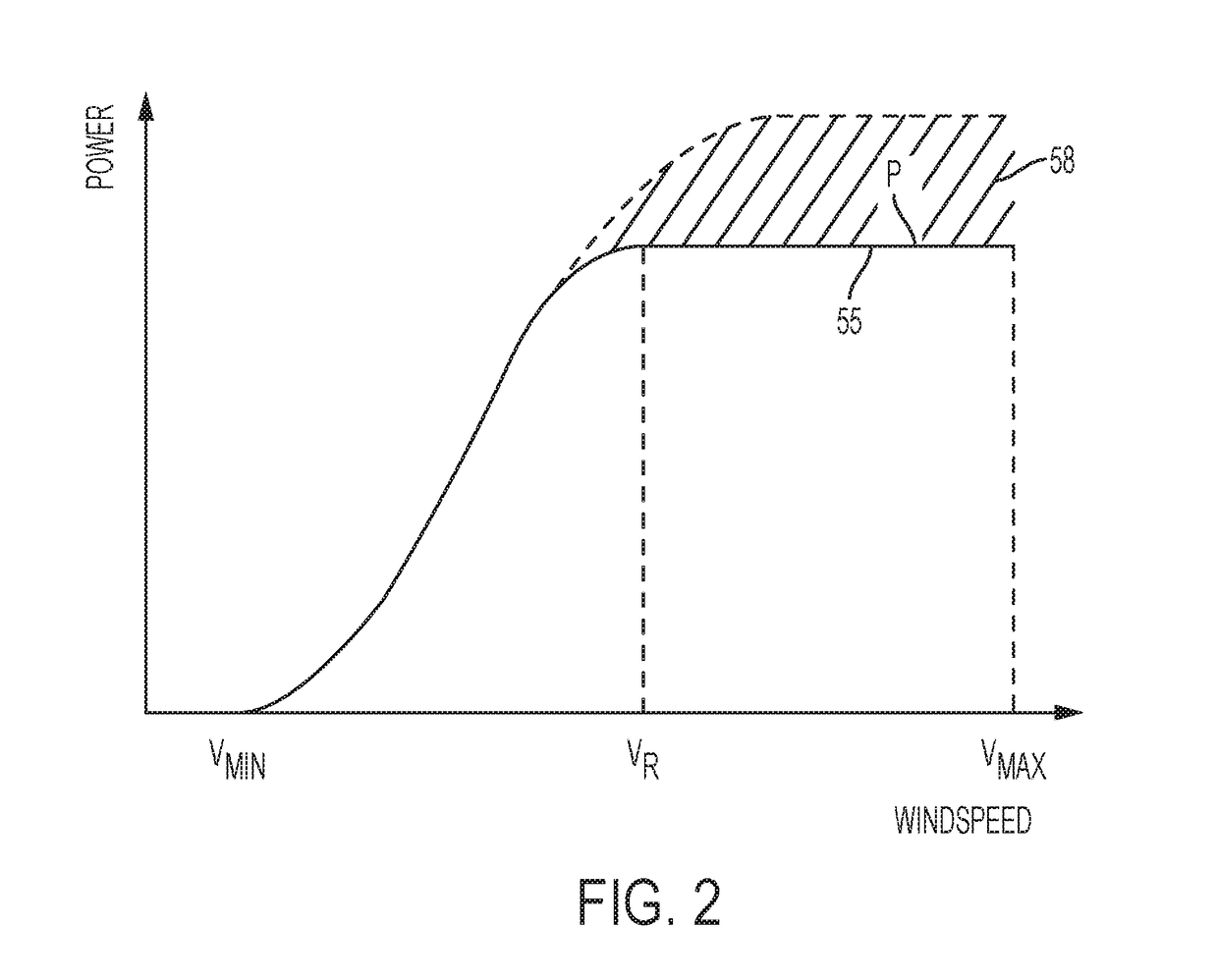
[0041]According to embodiments of the invention, an over-rating control signal is generated by an over-rating controller and is used by a wind turbine controller to over-rate the turbine. The specific manner in which over-rating control signals are generated is not crucial to embodiments of the present invention, but an example will be given for ease of understanding.

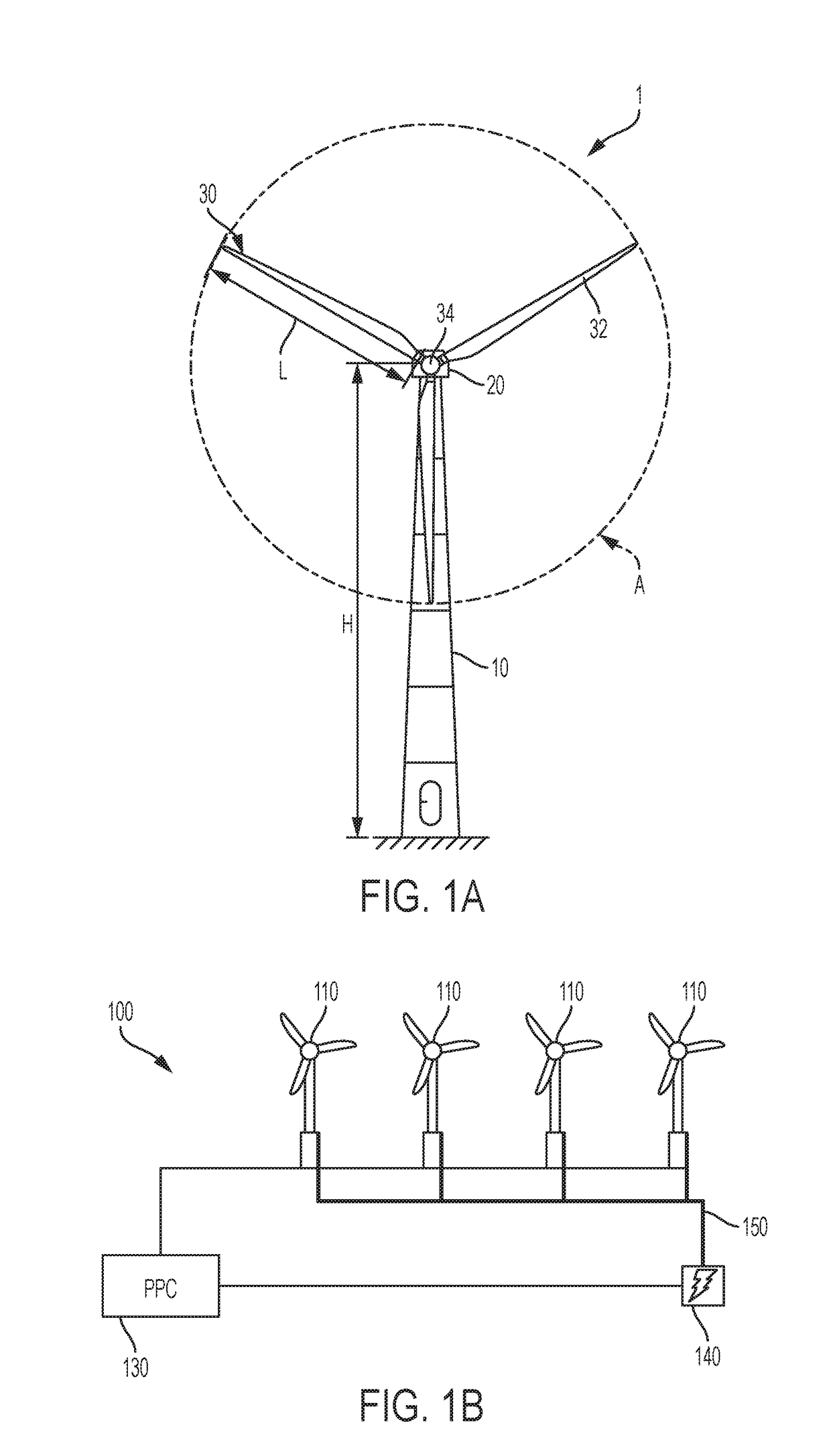
[0042]Each wind turbine may include an over-rating controller, as part of the wind turbine controller. The over-rating controller calculates an over-rating request signal indicating an amount up to which the turbine is to over-rate the power output above rated output. The controller receives data from the turbine sensors, such as pitch angle, rotor speed, power output etc and can send commands, such as set points for pitch angle, rotor speed, power output etc. The controller may also receive commands from the grid, for example from the grid operator to boost or reduce active or reactive power output in response to deman...


PUM


Abstract

A method is provided of controlling a wind turbine that is operating according to a control signal causing the wind turbine to be over-rated above the wind turbine's rated power. The method comprises: obtaining one or more signals, or values of variables, that indicate the fatigue lifetime of one or more of the wind turbine's components from turbine sensors; applying a lifetime usage estimator algorithm to the signals or values to determine measures of the fatigue life consumed by each of the turbine components; calculating, for each of the turbine components, a rate of consumption of fatigue life based on the measures of the fatigue life consumed by each of the turbine components; and controlling the turbine to reduce the amount of power by which the wind turbine is over-rated based on the rate of consumption of fatigue life for at least one of the turbine components.

Description

[0001]Embodiments of the present invention relate to a method and control system for use in protecting a wind turbine from severe operating conditions such as short term weather events.[0002]FIG. 1A illustrates a large conventional wind turbine 1, as known in the art, comprising a tower 10 and a wind turbine nacelle 20 positioned on top of the tower 10. The wind turbine rotor 30 comprises three wind turbine blades 32 each having a length L. The wind turbine rotor 30 could comprise another number of blades 32, such as one, two, four, five, or more. The blades 32 are mounted on a hub 34 which is located at a height H above the base of the tower. The hub 34 is connected to the nacelle 20 through a low speed shaft (not shown) extending from the front of the nacelle 20. The low speed shaft drives a gearbox (not shown) which steps up the rotational speed and, in turn, drives an electrical generator within the nacelle 20 for converting the energy extracted from the wind by the rotating bla...

Claims


Application Information

Patent Timeline
Patent Type & Authority Applications(United States)
IPC IPC(8): F03D7/02F03D7/04
CPCF03D7/0292F03D7/048F05B2270/1033F05B2270/332F03D7/028Y02E10/72
Inventor SPRUCE, CHRIS
Owner VESTAS WIND SYST AS
Why Eureka
Try Eureka