Segmented pitch ring for a wind turbine blade pitch system

Active Publication Date: 2018-06-07
VESTAS WIND SYST AS
View PDF7 Cites 3 Cited by
  • Summary
  • Abstract
  • Description
  • Claims
  • Application Information

AI Technical Summary

Benefits of technology

[0021]The bridge element may be formed from a material having a higher strength than the material used to form the one or more rolled segments. This ensures that high stresses experienced by one of the rolled segments do not result in deformation of the bridge element across the junction between segments.
[0022]Optionally, the one or more casted segments define mounting portions for a pitch drive mechanism. The relatively complex shape of such mounting portions is more suitable to be formed by casting, and so this contributes to the ease of manufacture of the pitch ring. The inclusion of the mounting portions facilitates connection of the pitch drive mechanism to the pitch ring.
[0023]The segmented pitch ring may comprise first and second substantially identical and diametrically opposed casted segments and first and second substantially identical and diametrically opposed rolled segments. This provides a symmetry between opposing sides of the pitch ring, reducing the risk of weak points around the circumference. This also minimises the amount of segments needed so that the more complex-shaped parts of the pitch ring are casted but the remainder of the pitch ring is formed by a rolling process. In the case where the casted segments include mounting portions for receiving a pitch drive mechanism, the symmetrical arrangement ensures that the stresses involved in pitching the blade are evenly distributed around the pitch ring.
[0024]The segmented pitch ring may comprise a beam connected between first and second diametrically opposed casted segments. Such a beam further increases the structural integrity of the pitch ring. The beam is preferably a hollow, elongate member. The beam preferably has a substantially uniform cross-section. The bea

Problems solved by technology

Current blade pitch rings are typically casted as a single part or piece, and it becomes problematic for blade pitch rings of ever larger diam

Method used


Image

  • Segmented pitch ring for a wind turbine blade pitch system
  • Segmented pitch ring for a wind turbine blade pitch system
  • Segmented pitch ring for a wind turbine blade pitch system

Examples


Example

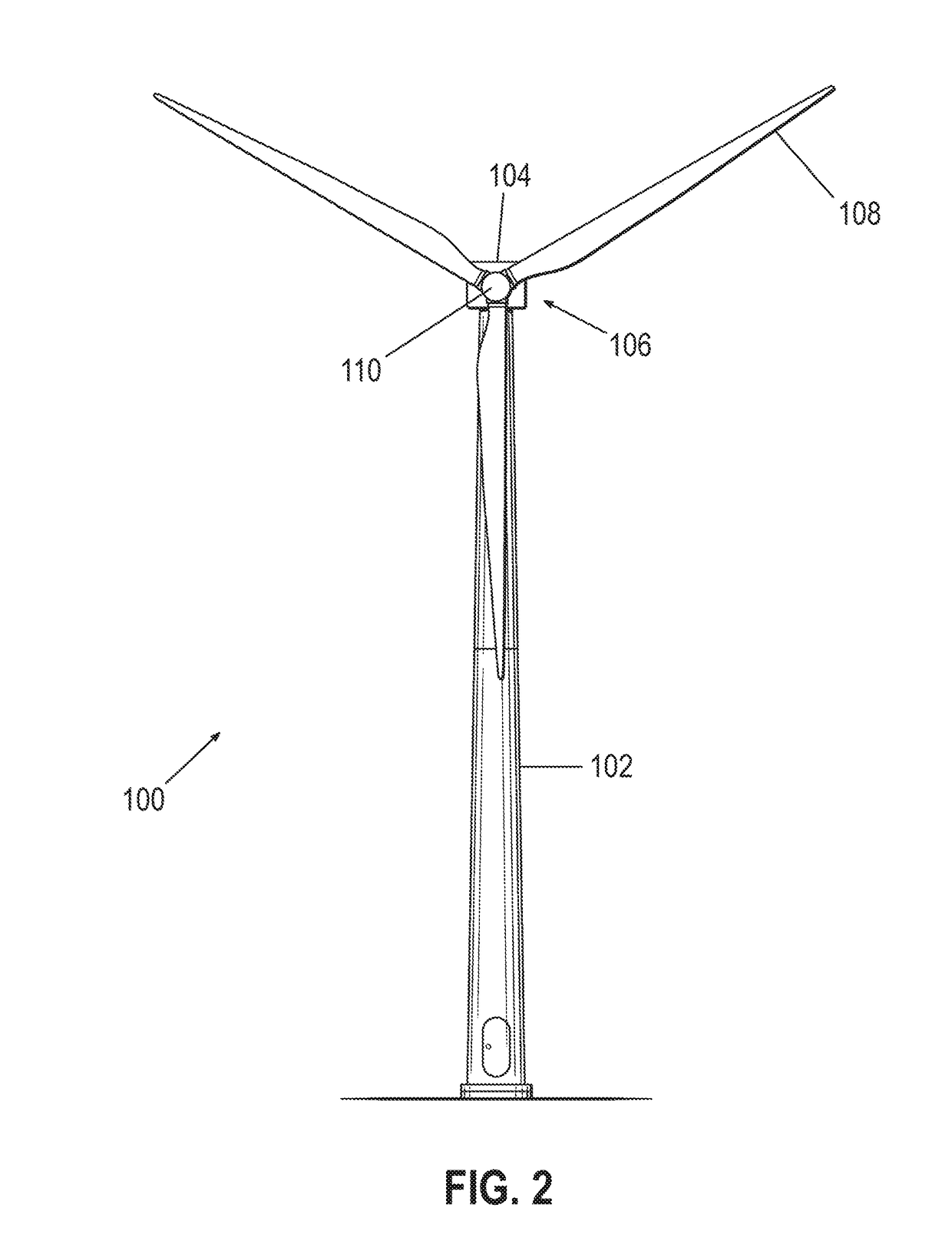
[0044]FIG. 2 is a front view of a wind turbine 100 according to the present invention. The wind turbine 100 comprises a tower 102, a nacelle 104 located at the top of the tower 102, and a rotor-hub assembly 106 mounted to the nacelle 104. The rotor-hub assembly 106 comprises three turbine blades 108 affixed to a central hub 110. The blades 108 are arranged to cause rotation of the rotor-hub assembly 106 when wind is incident on the blades 108 in a direction substantially perpendicular to and into the plane of the page. The central hub 110 is connected to a main shaft housed in the nacelle 104, which in turn is connected to a generator also in the nacelle 104. The central hub 110 causes the main shaft to turn and this rotational energy is converted into electricity by the generator.

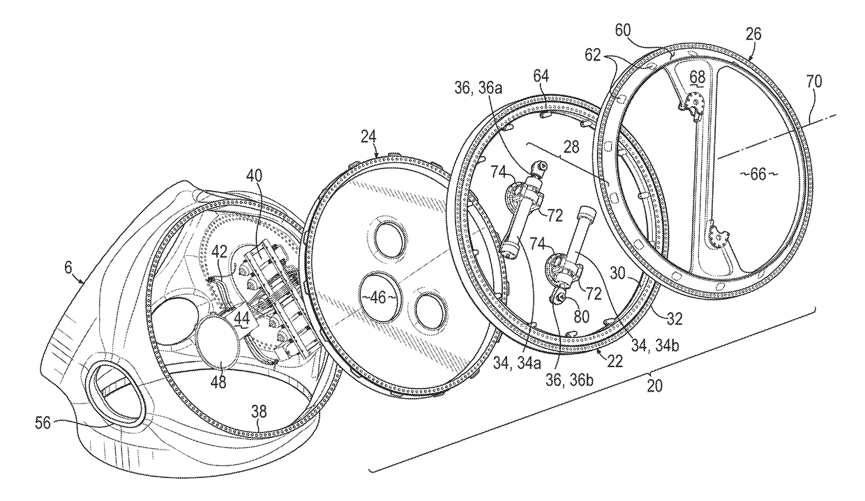
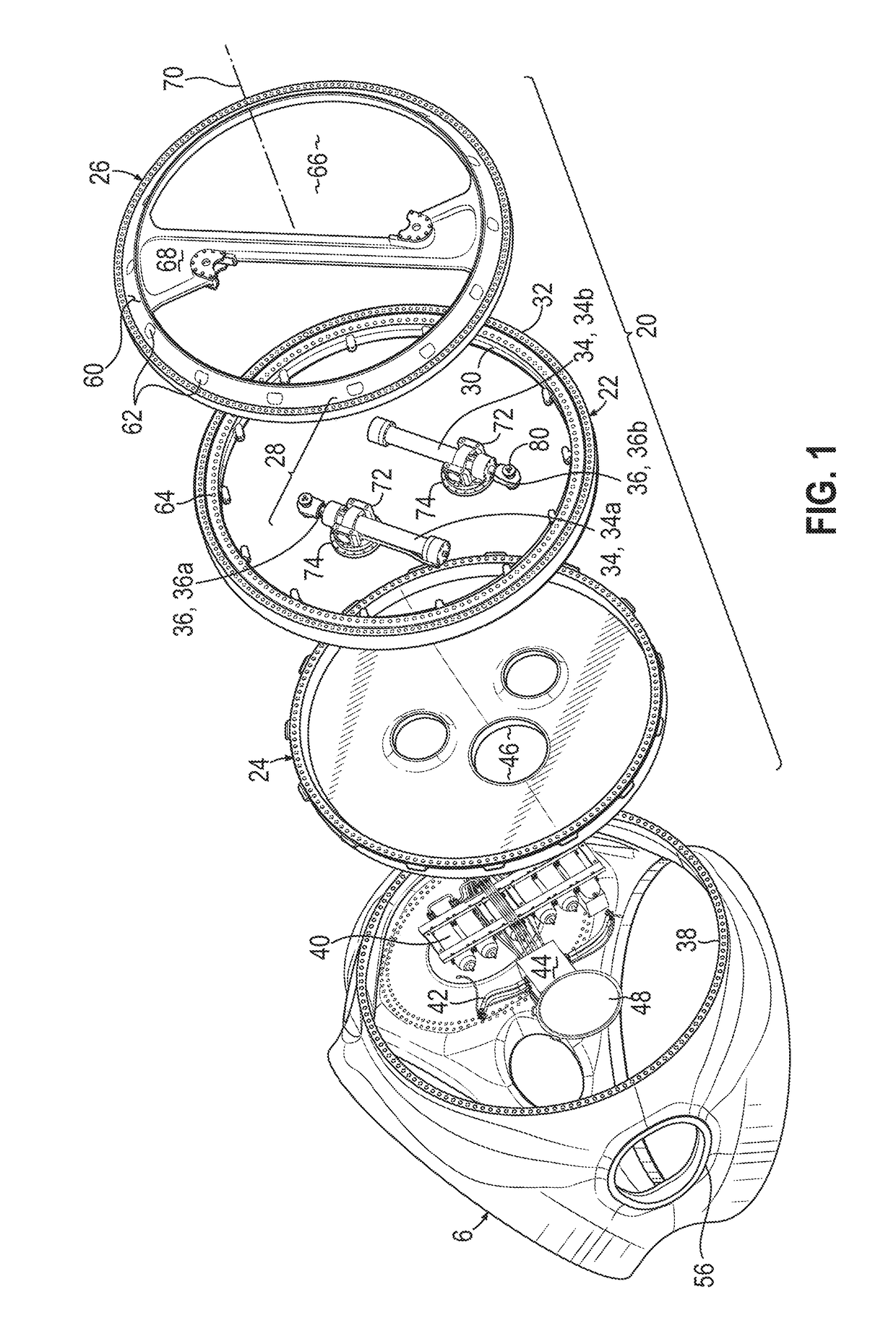
[0045]Each wind turbine blade 108 is mounted to the central hub 6 by a pitch system similar to the pitch system described by way of background with reference to FIG. 1. Accordingly, reference to FIG. 1 sho...


PUM


Abstract

The present invention provides a segmented pitch ring for use in a blade pitch system of a wind turbine. The segmented pitch ring is formed of a plurality of segments manufactured by different processes. In particular, one or more of the segments are formed by a rolling process, and one or more of the segments are formed by a casting process. The segments are arc-shaped or include arc-shaped sections that in combination define a substantially circular circumference of the pitch ring.

Description

TECHNICAL FIELD[0001]The present invention relates generally to wind turbines and more specifically to a pitch ring for use in a blade pitch system of a wind turbine. The invention also relates to a method of making a pitch ring.BACKGROUND[0002]Wind turbines typically include a rotor with large blades driven by the wind. The blades convert the kinetic energy of the wind into rotational mechanical energy. Typically, the mechanical energy is transferred via a drive train to a generator, which then converts the energy into electrical power.[0003]Most modern wind turbines control power output by pitching the blades relative to the wind. Thus, each blade is mounted to a hub by a pitch system that allows relative movement between the blade and the hub. The pitch system comprises a pitch bearing, which typically includes concentrically-arranged inner and outer bearing rings. One of the bearing rings (either the inner or the outer ring) is attached to the blade and the other is attached to ...

Claims


Application Information

Patent Timeline
IPC IPC(8): F03D80/70F03D7/02F03D1/06F16C33/60
CPCF03D80/70F03D7/0224F03D1/0658F16C33/60F05B2230/21F05B2230/26F05B2260/79F16C2360/31F05B2240/50Y02E10/72Y02P70/50
Inventor CHRISTENSEN, MICHAELKABUS, SIMONMARKUSSEN, ERIKNEUBAUER, JESPER LYKKEGAARD
Owner VESTAS WIND SYST AS
Why Eureka
Try Eureka