
Multilayer damping material

a technology of damping material and multi-layer, applied in the direction of shock absorbers, mechanical equipment, transportation and packaging, etc., can solve the problems of mechanical vibration propagation through the body of the vehicle, noise can transform into air borne noise, and mechanical energy dissipation

Active Publication Date: 2018-06-07
3M INNOVATIVE PROPERTIES CO
View PDF4 Cites 19 Cited by
  • Summary
  • Abstract
  • Description
  • Claims
  • Application Information

AI Technical Summary

Benefits of technology

The invention provides a material or system that can reduce vibration and noise on surfaces of vehicles, appliances, and machines. It can help to make these surfaces quieter and more stable.

Problems solved by technology

The engine, drive train and other portions of a vehicle (e.g., automobiles, airplanes, motorboats, etc.) can generate mechanical vibrations that propagate through the body of the vehicle as structure borne noise.
Such structure born noise can transform into air borne noise.
The deformation of the body panel and attached viscoelastic layer can lead to stretching and / or compressing of the polymer chains within the viscoelastic material, resulting in the dissipation of mechanical energy in the form of, e.g., structural borne vibration (e.g., from the engine, tire / road interactions, compressors, fans, etc.) and the damping of vibrations.
When the constraining layer is attached on top of the viscoelastic material layer, each deformation of the panel leads not only to stretching and compressing of the polymer chains within the dissipating layer but also to shear within the dissipating layer.
The materials used for constraining layer add weight to the damping material which might be a problem, when used in a vehicle.
They also add bending stiffness to the damping material, which may lead to challenges, when applying the CLD material to complex shaped structures.

Method used


Image

  • Multilayer damping material
  • Multilayer damping material
  • Multilayer damping material

Examples


examples

[0136]The effect of stand-off damping using a kinetic spacer layer comprising multiple spacer elements according to the claims has been demonstrated with 3 different structures as kinetic spacer layer in two orientations.

Sample Preparation:

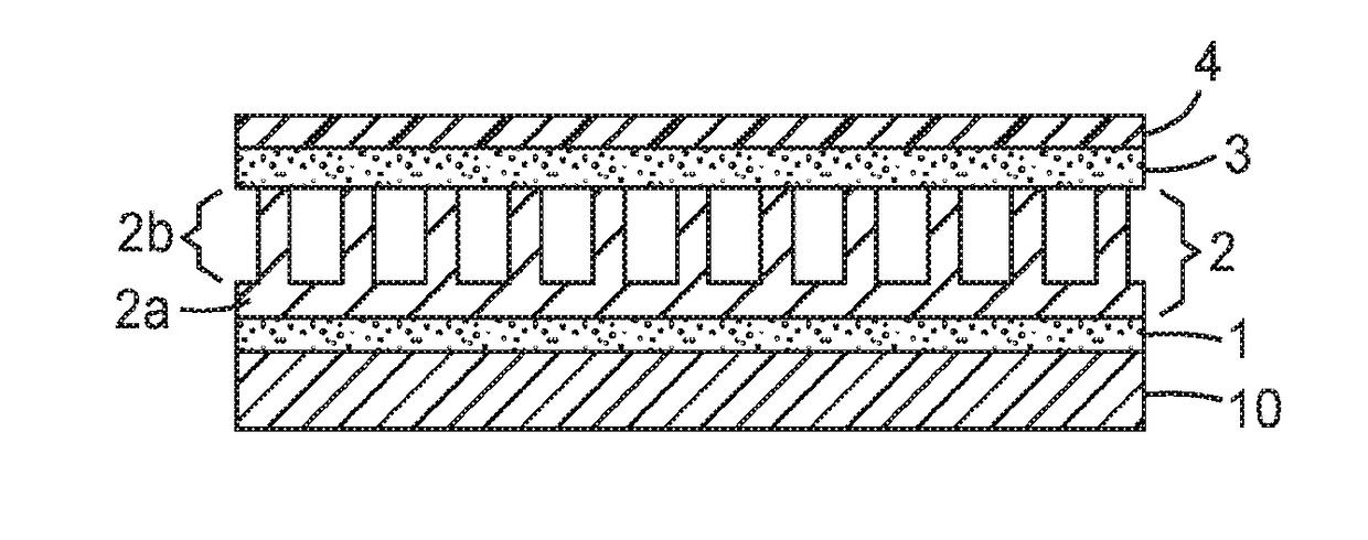
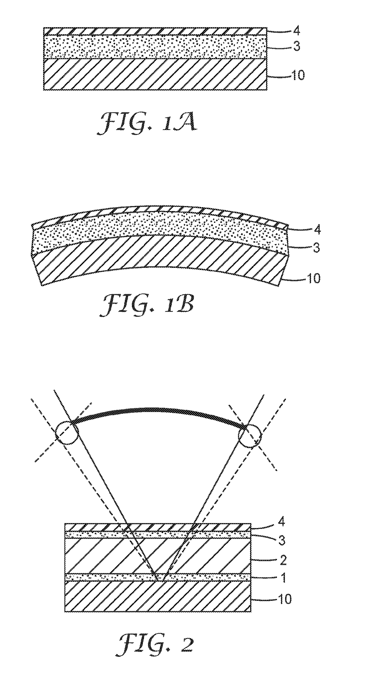
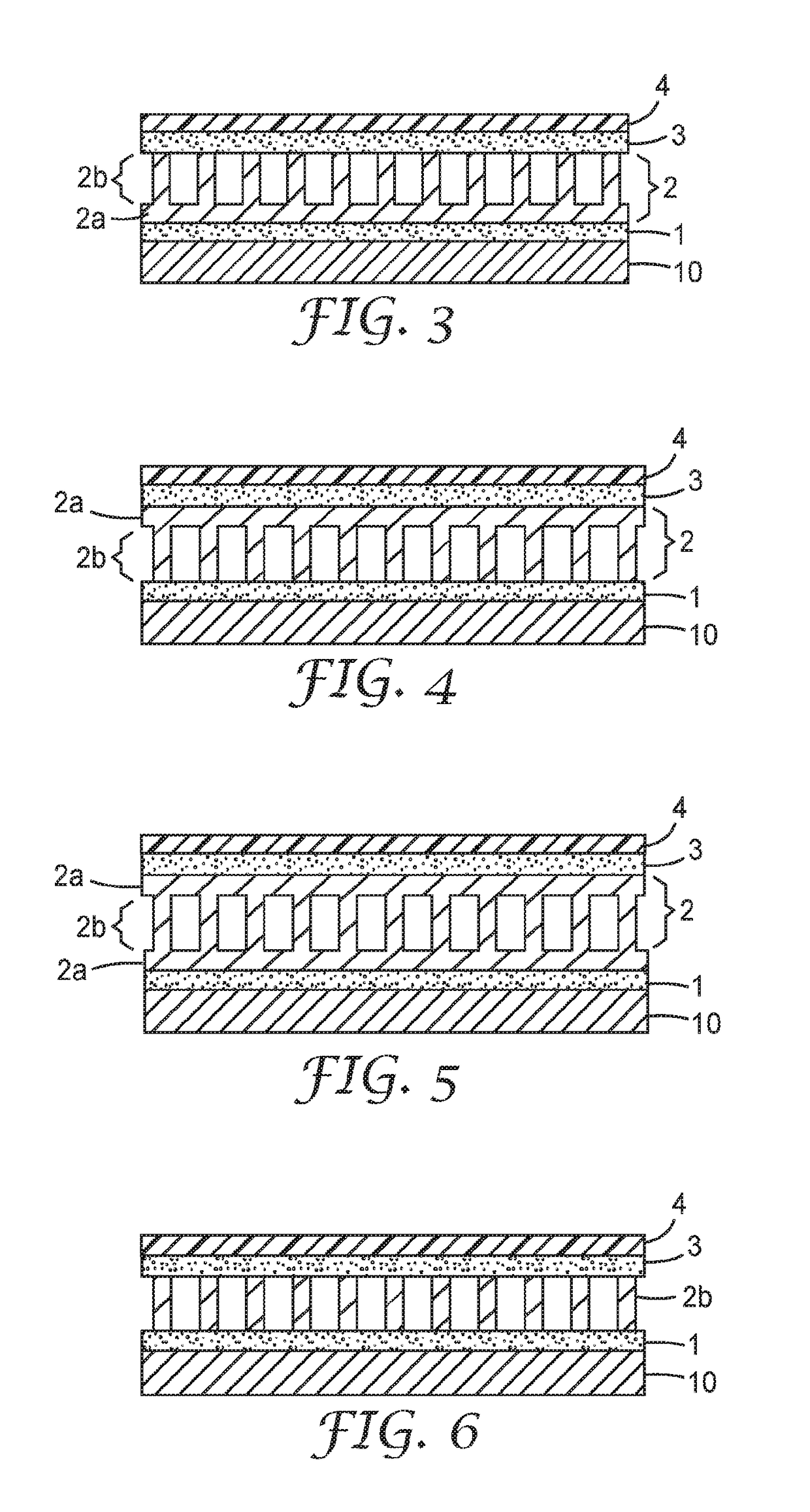
[0137]FIGS. 3 and 4 show the principle structure of the samples and the orientation of the different layers. The kinetic spacer elements are either extending from the base layer 2a into the direction of the panel 10 (pins down) or they are facing into the direction away from the panel 10 (pins up). Details of the materials used for the samples are shown in table 1. For the tests the panel 10 of FIGS. 3 and 4 is replaced by a below described steel beam for Oberst measurement.

[0138]Three different kinetic spacer layers were tested as well as a commercially available damping material.

Samples A-1 and A-2

[0139]A web made as described in U.S. Pat. No. 5,792,411 that comprises cylindrical stem elements that have a diameter of about 0.76 mm that are space...

example measurement

[0144]The damping behaviour of the examples was measured using the Oberst method according to DIN 53440 and ISO 5721. Using this method, the damping performance is determined by vibrational excitation of a steel beam covered with damping material and clamped at the uncovered end. The system damping loss factor can be calculated from the shape and width of so called transfer functions at bending resonance modes.

[0145]The measurements were performed in an environmental chamber at temperatures between 0° C. and 60° C. with a temperature increment of 20° C.

[0146]The results are shown in FIGS. 20 (pins up) and 21 (pins down). The damping performance at the bending resonance orders 2, 3, and 4 is plotted for the mentioned evaluation temperatures. Although having a lower weight / area, the damping loss factor of sample A is equal or higher compared with the commercial 3M Vibration Control Tape CL1151. Samples B and C show a much bigger damping performance compared with CL1151 which clearly d...


PUM

PropertyMeasurementUnit
thicknessaaaaaaaaaa
angleaaaaaaaaaa
diameteraaaaaaaaaa

Abstract

A multilayer damping material for damping a vibrating surface comprising: at least one constraining layer; at least one dissipating layer; and at least one kinetic spacer layer comprising multiple spacer elements. The kinetic spacer layer is arranged between the constraining layer and the vibrating surface, when used for damping the vibrating surface. Each spacer element has opposite ends. At least one end of each of the multiple spacer elements is embedded in, bonded to, in contact with, or in close proximity to the dissipating layer, such that energy is dissipated within the multilayer damping material, through movement of the at least one end of each of the multiple spacer elements.

Description

FIELD OF THE INVENTION[0001]The invention relates to a multilayer damping material for damping a vibrating surface, in particular to a damping material comprising at least one constraining layer, at least one dissipating layer and at least one kinetic spacer layer, and more particularly to such a damping material where the kinetic spacer layer comprises multiple spacer elements arranged between the constraining layer and the vibrating surface, when used for damping the vibrating surface.BACKROUND[0002]The engine, drive train and other portions of a vehicle (e.g., automobiles, airplanes, motorboats, etc.) can generate mechanical vibrations that propagate through the body of the vehicle as structure borne noise. Such structure born noise can transform into air borne noise. It can be useful to damp these structural vibrations before their kinetic energy is radiated as air borne noise into other vehicle areas (e.g., inside a passenger compartment).[0003]Typically, one or more applicatio...

Claims


Application Information

Patent Timeline
Patent Type & Authority Applications(United States)
IPC IPC(8): F16F9/30B60R13/08B32B3/30B32B3/26B32B7/12B32B15/085B32B15/20B32B1/00
CPCF16F9/306B60R13/0815B32B3/30B32B3/266B32B7/12B32B15/085B32B15/20B60R13/0212B60R13/0243B60R13/0256B62D25/20F16F2234/06F16F2226/042B32B2307/102F16F1/3737
Inventor ALEXANDER, JONATHAN H.EICHHORN, GEORGGERDES, RONALD W.HANSCHEN, THOMAS P.HERDTLE, THOMASYOO, TAEWOOK
Owner 3M INNOVATIVE PROPERTIES CO
Learn More