Power cable

a power cable and cable body technology, applied in the direction of power cables, cables, insulated conductors, etc., can solve the problems of reducing the lifespan of power cables, reducing the adhesion strength of foils, and reducing the corrosion resistance of aluminum foils, so as to reduce the weight of foils, reduce the risk of corrosion, and improve the adhesion strength

Active Publication Date: 2018-06-07
LS CABLE & SYST LTD
View PDF15 Cites 2 Cited by
  • Summary
  • Abstract
  • Description
  • Claims
  • Application Information

AI Technical Summary

Benefits of technology

[0013]A power cable according to the present invention includes a watertight layer formed of a lightweight material and is thus lighter in weight than existing power cables.
[0014]A power cable according to the present invention includes a watertight layer formed of a material having a high corrosion resistance to be suppressed from being corroded.
[0015]A power cable according to the present invention additionally includes an adhesive layer for improving adhesion strength between a watertight layer and an external jacket and effectively suppressing permeation of moisture which is a major factor decreasing the adhesion strength between the watertight layer and the external jacket to effectively suppressing the watertight layer from being peeled regardless of externally physical impact and a temperature change, thereby maintaining the function of the watertight layer and suppressing a decrease in the lifespan of the power cable.

Problems solved by technology

Here, when an aluminum laminated tape in which both sides of aluminum foil are coated with polyethylene is used as the watertight layer 7, the aluminum foil is likely to corrode and may be thus damaged by moisture penetrating the external jacket 6, thereby reducing the lifespan of the power cable.
Here, when a lead laminated tape in which both sides of lead foil are coated with polyethylene, polyvinyl chloride, or the like is used as the watertight layer 7′, the lead foil is heavy in weight and may thus prevent the manufacture of a lightweight power cable.

Method used


Image

  • Power cable
  • Power cable
  • Power cable

Examples


preparation examples

1. Preparation Examples

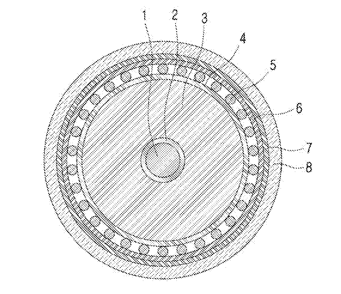
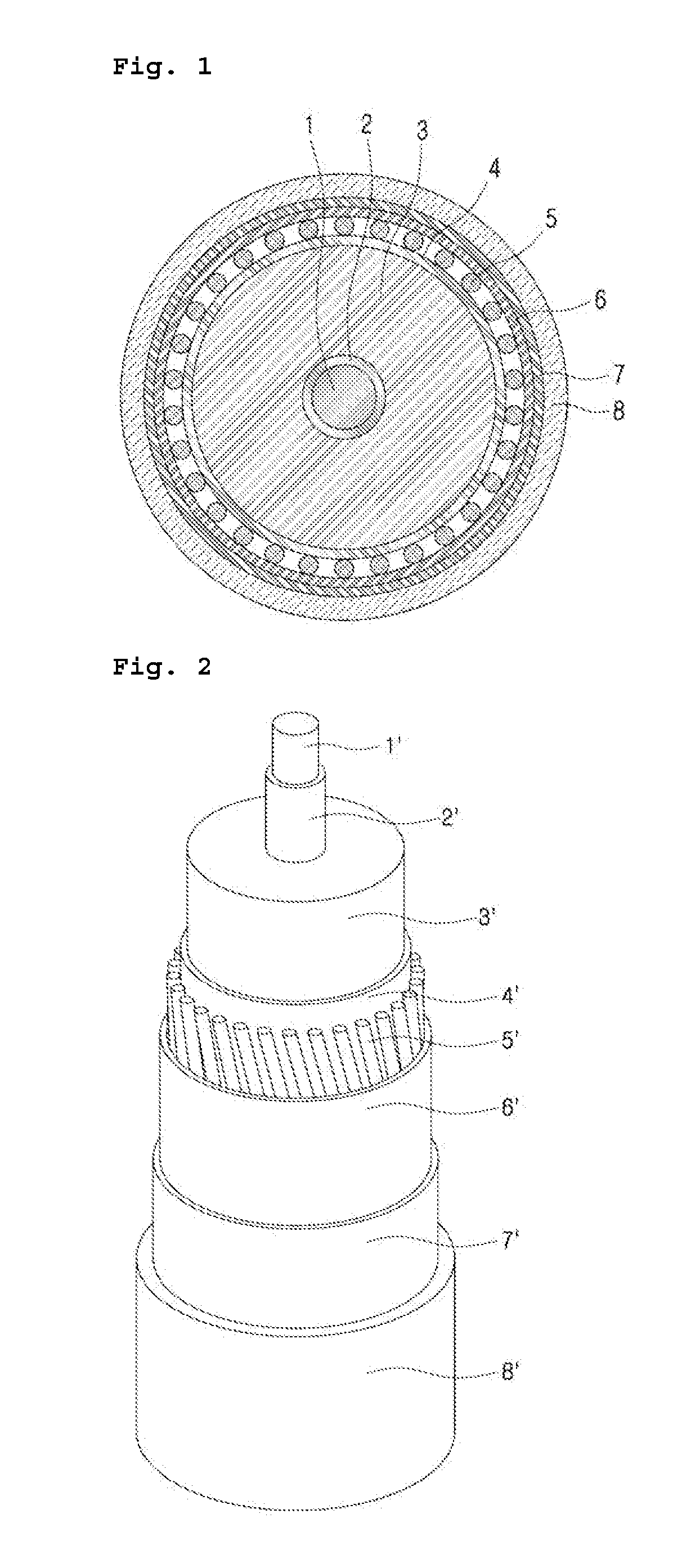
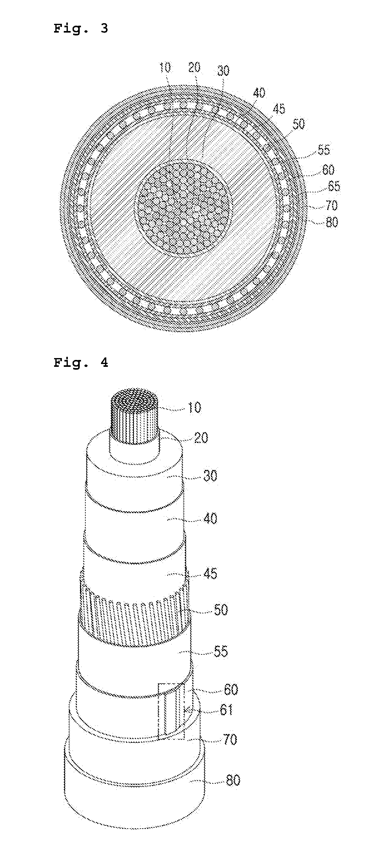
[0069]A sample sheet according to Example 1 was manufactured by sequentially stacking an adhesive layer (high-density polyethylene having a density of 0.956), a copper tape, an adhesion assisting layer (ethylene vinyl acetate), an adhesive layer (high-density polyethylene having a density of 0.956), and an external jacket (high-density polyethylene, carbon black 2.5 weight %) through a hot pressure work under conditions of press temperature 160° C. (ten minutes), cooling temperature 40° C. (ten minutes), and pressure of 4,800 kg / m2. Furthermore, sample sheets according to examples and comparative examples were manufactured, in which litmus paper was inserted between two samples of adhesive layers shown in Table 1 below.

TABLE 1ResinThickness (mm)Example 2Resin 11.0Example 3Resin 12.0Example 1Resin 10.25Example 2Resin 10.5Example 3Resin 20.25Example 4Resin 20.5Example 5Resin 21.0Example 6Resin 22.0resin 1: high-density polyethylene (density: 0.956)resin 2: ethyl...


PUM

PropertyMeasurementUnit
thicknessaaaaaaaaaa
softening temperatureaaaaaaaaaa
degree of crystallinityaaaaaaaaaa

Abstract

The present invention relates to a power cable. More particularly, the present invention relates to a power cable which is, when compared to the existing power cables, lightweight and includes a watertight layer which improves a corrosion resistance and is effectively suppressed from being peeled since the interlayer adhesiveness thereof is maintained regardless of an externally physical impact and a temperature change.

Description

TECHNICAL FIELD[0001]The present invention relates to a power cable. More particularly, the present invention relates to a power cable which is, when compared to the existing power cables, lightweight and includes a watertight layer which improves a corrosion resistance and is effectively suppressed from being peeled since the interlayer adhesiveness thereof is maintained regardless of an externally physical impact and a temperature change.BACKGROUND ART[0002]Generally, power cables such as a submarine cable and an underground cable include a watertight layer which suppresses permeation of moisture from the outside.[0003]FIG. 1 schematically illustrates a structure of a cross section of the power cable disclosed in U.S. Pat. No. 4,472,597. As illustrated in FIG. 1, the power cable according to the related art may have a structure in which a conductor 1, an inner semiconducting layer 2, an insulating layer 3, an outer semiconducting layer 4, a metal shield layer 5, a conductive tape ...

Claims


Application Information

Patent Timeline
Patent Type & Authority Applications(United States)
IPC IPC(8): H01B7/28C09J123/06C09J123/08C09J133/02C09J7/35C09J5/06C09J7/24H01B7/18H01B7/22H01B9/02H01B19/04
CPCH01B7/2806C09J123/06C09J123/0869C09J133/02C09J7/35C09J5/06C09J7/243H01B7/187H01B7/226H01B9/027H01B19/04C09J2203/302C09J2400/16C09J2423/04C09J2423/041C09J2433/00H01B7/28
Inventor LEE, JAE IKYOO, WON SANGKIM, KWANG MOKANG, SUNG TAELEE, TAE HYUN
Owner LS CABLE & SYST LTD
Why Eureka
Try Eureka