
Hearing aid

a hearing aid and hearing aid technology, applied in the field of hearing aids, can solve the problems of device discomfort, insufficient or inconvenient use of air conduction hearing aids, and hearing impairmen

Active Publication Date: 2018-06-07
SRIS TECH LTD
View PDF4 Cites 15 Cited by
  • Summary
  • Abstract
  • Description
  • Claims
  • Application Information

AI Technical Summary

Benefits of technology

The invention is about a device that prevents the magnetic mass from hitting the housing during movement in certain directions. The device includes elastic members that hold the magnetic mass in place and reduce friction and wear during use. The technical effect of this invention is to protect the magnetic mass and improve the performance of the device.

Problems solved by technology

Hearing impairment can be due to problems in one or more of the outer, middle and inner ears which together form the human auditory system.
However, for certain ear canal and middle ear disorders (e.g. congenital malformations, ossicular discontinuity, otosclerosis, a perforated tympanic membrane, or chronic ear infections) air conduction hearing aids cannot be used or are insufficient.
Such devices can be uncomfortable due to the static force required to adequately couple the vibrator unit to the skull and suffer from reduced high frequency sensitivity due to the attenuation effect of soft tissue overlying the skull, as well as feedback problems due to sound radiation from the vibrator unit being picked up by the microphone of the hearing aid.
The bone anchor may also suffer from problems and can be damaged through injury.
Some patients will refuse a BAHA because they cannot tolerate a skin penetration implant for personal reasons or social stigma.
BCI devices bring their own set of problems.
The area of skin overlying the implanted unit must be kept free of hair which for most patients means regular shaving and an unsightly bald patch.
The external unit is prone to falling off when the wearer performs physical activity and can be easily knocked off.
Even so, the strength of the magnet used to hold the external unit in place leads to compression of the skin, leading to irritation and potentially pressure sores.
The operation required to install the implanted unit behind the ear in the temporal bone carries a high risk of facial nerve or vestibular damage.
The implanted unit must also be removed should the patient require an MRI scan, which necessitates another risky operation.
Even if the patient is not harmed by the action of the strong magnetic field present in an MRI scanner on the implanted unit, the implanted unit is likely to be damaged (e.g. due to demagnetisation of the biasing magnets of the vibrator).
The MRI images in the region of the implanted unit would in any case be heavily distorted due to the presence of biasing magnets in the vibrator.
Such an arrangement is not suitable for use in patients with unilateral hearing loss due to problems in the middle or inner ear because the device does not generate vibrations in the temporal bone which can be conducted across the skull to the functional cochlea.
The surgical risks associated with the implantation of a BCI device provided with a vibrating unit for attachment into the middle ear is even greater than the risks associated with installing conventional BCI devices.
Operating on the middle ear increases the risk of infection and is a difficult operation to perform due to the very small size of the ossicles.
Furthermore, even with the implanted unit removed and the vibrating units adapted to present a low magnetic moment, it is risky for a patient to undergo an MRI scan because of the fragility of the ossicles and the soft structures of the middle and inner ear.
This design suffers from several problems, most notably poor performance due to the low coupling of vibrations into the mastoid bone due to absorption by the casing of the hearing aid and the soft tissues lining the ear canal.
This leads to irritation of the lining of the ear canal and potentially pressure sores.
Since the hearing aid blocks the ear canal, use of the device creates conditions in the ear which can lead to infection.
Finally, and significantly to wearers of the device, the vibration of the device in the ear causes a tickling sensation in the ear of the wearer which for some patients means using the device for extended periods of time is not an option.

Method used


Image

  • Hearing aid
  • Hearing aid
  • Hearing aid

Examples


Embodiment Construction

[0085]The following description is presented by way of example to enable any person skilled in the art to make and use the invention. The present invention is not limited to the embodiments described herein and various modifications to the disclosed embodiments will be readily apparent to those skilled in the art.

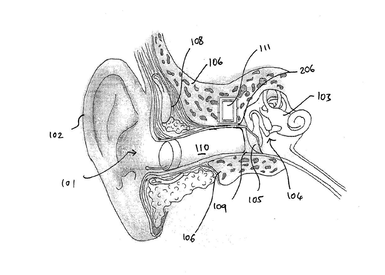
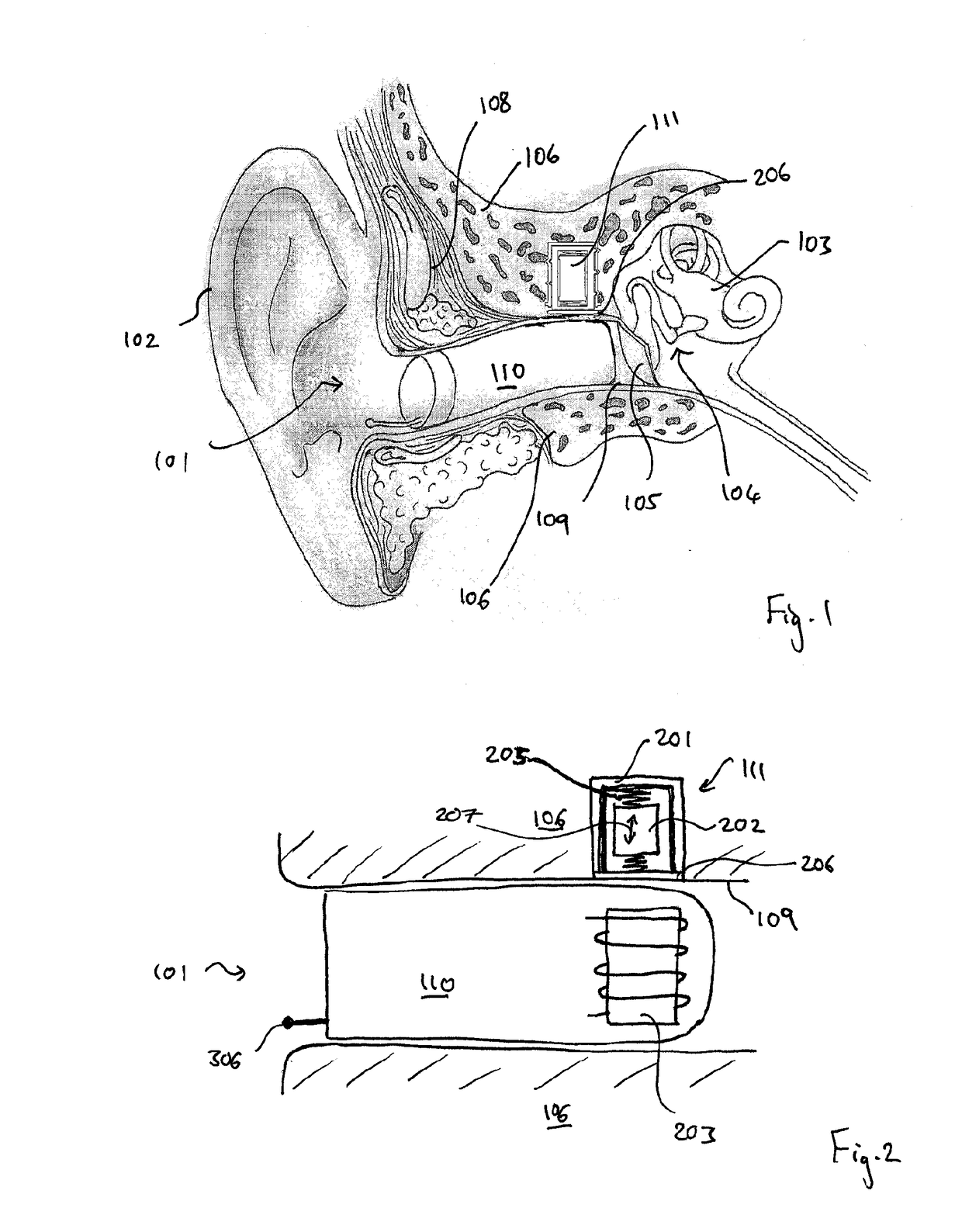
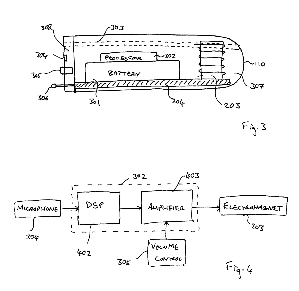
[0086]There is provided improved apparatus for assisting hearing in humans and animals which addresses the shortcomings of conventional hearing aid devices. There is also provided a bone implant which represents improved apparatus for coupling vibrational energy into the temporal bone. There is also provided a hearing aid device adapted for wear in the ear canal and for inducing vibration in the bone implant.

[0087]A cross-sectional representation of the human ear is shown in FIG. 1. The ear canal 101 provides a channel along which environmental sounds captured by the auricle 102 are directed to the tympanic membrane 105. Vibrational movement of the tympanic membrane leads t...


PUM


Abstract

Apparatus for assisting hearing, the apparatus comprising: an in-ear component for insertion into the ear canal and comprising an electromagnet; and a bone implant for mounting in the temporal bone bordering the ear canal, the bone implant comprising a housing and a magnetic mass suspended within the housing such that vibrations of the magnetic mass are mechanically coupled into the housing; wherein the in-ear component is configured to drive its electromagnet so as to, when the in-ear component is located in an ear canal with the electromagnet adjacent to the bone implant, cause the magnetic mass to vibrate within the housing.

Description

BACKGROUND OF THE INVENTION[0001]This invention relates to apparatus for assisting hearing in humans and animals, a bone implant and a hearing aid device.[0002]A significant proportion of the population suffer some form of hearing impairment. This can be due to a variety of factors, including as a result of disease, genetic conditions, congenital malformations, removal of an acoustic neuroma and trauma. Hearing impairment can be due to problems in one or more of the outer, middle and inner ears which together form the human auditory system. Hearing impairment may be bilateral (on both sides of the head) or unilateral (occurring on only one side of the head).[0003]Various devices have been developed to address hearing impairment. For patients with mild hearing loss, commonplace air conduction hearing aids are often sufficient. Air conduction hearing aids provide amplified sound into the ear canal so as to compensate for reduced hearing sensitivity. Sound pressure delivered through th...

Claims


Application Information

Patent Timeline
IPC IPC(8): H04R25/00
CPCH04R25/606H04R2225/025H04R2460/13H04R2225/67
Inventor SRISKANDARAJAH, SATHEESH
Owner SRIS TECH LTD
Learn More