

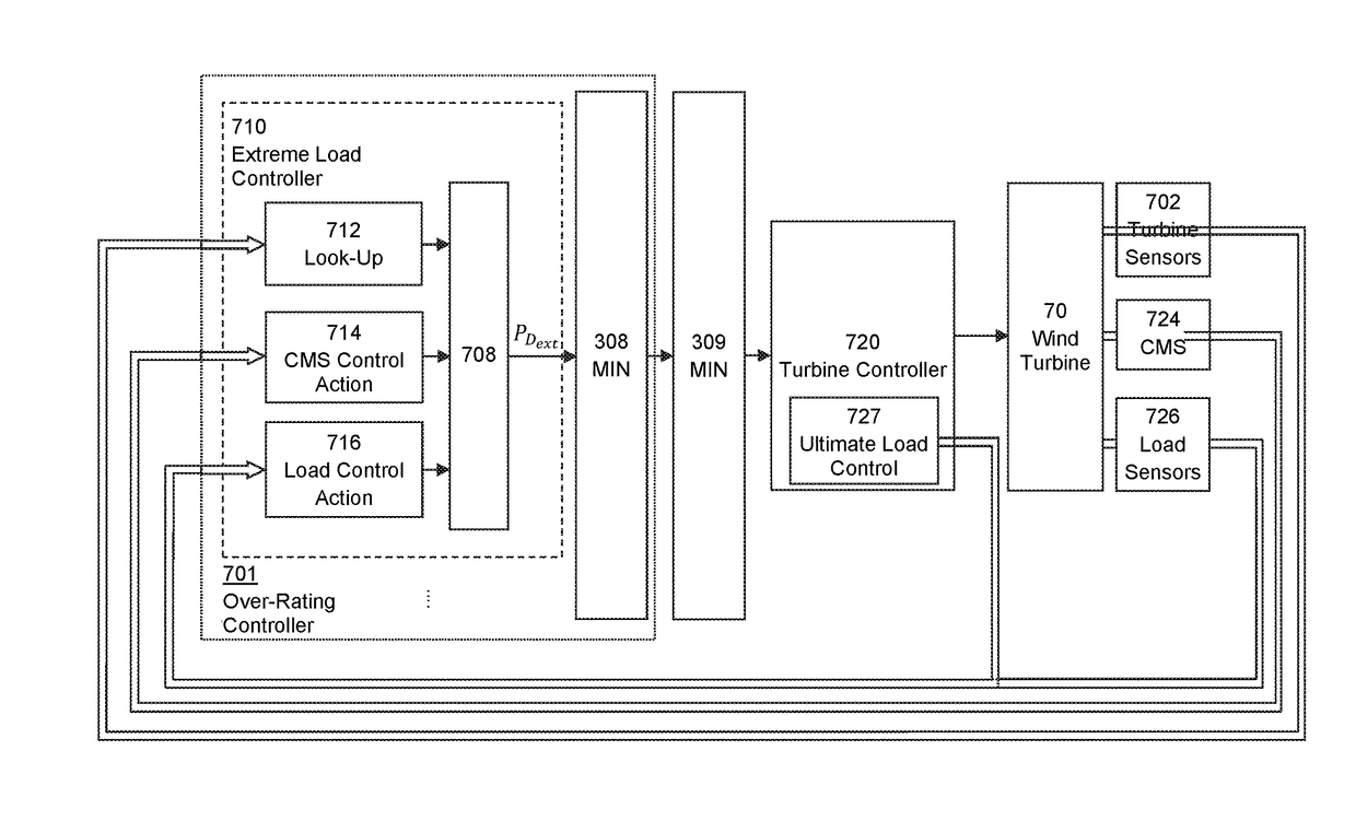
Extreme load control
a load control and load technology, applied in the direction of motors, engine control parameters, comparison table algorithms, etc., can solve the problems of increasing the risk of continuous delivery of power from the turbine, and the rate of wear or accumulation of damage, so as to achieve the effect of reducing the risk of exceeding the maximum load
- Summary
- Abstract
- Description
- Claims
- Application Information
AI Technical Summary
Benefits of technology
Problems solved by technology
Method used
Image

Examples
Embodiment Construction
[0041]A common approach to wind turbine design and, more particularly, to engineering a turbine to withstand the various loads it is expected to experience, is to consider in turn the various states or situations in which a turbine may be at any given time. Each of these so-called ‘load cases’ represents a design situation characterised by a set of loads and other conditions to be taken into account. The design load cases set out in IEC 64100-1 are given in Table 1 below. In the table, the letter ‘U’ in the penultimate column designates a load case analysed as an ultimate load case, and ‘F’ a fatigue load case.
[0042]As mentioned above, fatigue load cases are not the direct subject of this invention. The ultimate load cases can, for the purposes of the present discussion, be conveniently divided into three main classes. A first class includes non-operational load cases, such as the extreme (or 50-year) wind speed model (EWM) considered within the ‘Parked’ situation. These load cases ...
PUM
 Abstract
Description
Claims
Application Information