Vehicular lamp

Active Publication Date: 2018-06-28
KOITO MFG CO LTD
View PDF1 Cites 12 Cited by
  • Summary
  • Abstract
  • Description
  • Claims
  • Application Information

AI Technical Summary

Benefits of technology

[0038]With this embodiment, the comparator used in the error amplifier control mode and the comparator used in the hysteresis control mode can be configured as a single shared comparator. This allows the circuit area to be reduced.
[0039]The lighting circuit according to an embodiment may further comprise: a frequency detection circuit structured to generate a frequency detection signal that indicates a frequency of the control pulse; and a hysteresis width adjuster structured to change a voltage difference between the upper threshold signal and the lower threshold signal such that the frequency detection signal approaches a reference value. This arrangement is capable of s

Problems solved by technology

However, this leads to a problem of imparting glare to a pedestrian or otherwise a driver of a leading vehicle ahead of the vehicle.
However, in some cases, this arrangement has a

Method used


Image

  • Vehicular lamp
  • Vehicular lamp
  • Vehicular lamp

Examples


first embodiment

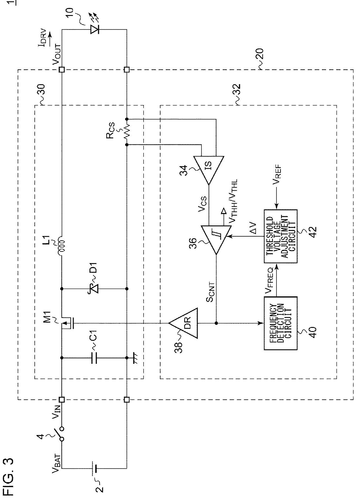
[0096]FIG. 3 is a block diagram showing a vehicular lamp 1 according to a first embodiment. The vehicular lamp 1 includes a semiconductor light source 10 and a lighting circuit 20. Examples of the semiconductor light source 10 include LEDs, LDs, organic EL (electroluminescence), and the like. However, the semiconductor light source 10 is not restricted in particular. The lighting circuit 20 includes a switching converter 30 and a converter controller 32. As with the arrangement shown in FIG. 1, the switching converter 30 is configured as a step-down converter. The converter controller 32 stabilizes the driving current IDRV which is supplied from the switching converter 30 to the semiconductor light source 10, to a predetermined target current IREF.

[0097]The converter controller 32 includes a current detection circuit 34, a hysteresis comparator 36, a driver 38, a frequency detection circuit 40, and a threshold voltage adjustment circuit 42. The current detection circuit 34 generates...

first modification

[First Modification]

[0123]FIGS. 10A and 10B are circuit diagrams each showing the frequency detection circuit 40 according to the first modification. In the frequency detection circuit 40 shown in FIG. 10A, the peak hold circuit 56 has a configuration that differs from that shown in FIG. 6. The peak hold circuit 56 includes a capacitor C81, a resistor R81, and a buffer 57. The buffer 57 is capable of functioning as a current source. However, the buffer 57 is not capable of functioning as a current sink. A peak voltage of the first periodic signal S11 occurs at the capacitor C81.

[0124]The frequency detection circuit 40 shown in FIG. 10B includes an averaging circuit 58 instead of the peak hold circuit 56. The averaging circuit 58 includes a buffer 59, a resistor R91, and a capacitor C91, for example. The resistor 91 and the capacitor C91 function as a low-pass filter, which averages the output of the buffer 59.

second modification

[Second Modification]

[0125]FIG. 11 is a block diagram showing a lighting circuit 20a according to a second modification. A converter controller 32a shown in FIG. 11 further includes a modulator 60 in addition to the converter controller 32 shown in FIG. 3. The modulator 60 superimposes a modulation signal VMOD having a frequency that is lower than the switching frequency of the switching transistor M1 on the reference value VREF that provides the target value of the switching frequency.

[0126]FIG. 12 is a circuit diagram showing an example configuration of the modulator 60. The modulator 60 includes an oscillator 62 that generates the modulation signal VMOD having a frequency that is sufficiently lower than the switching frequency. The modulator 60 changes the reference value VREF according to the modulation signal VMOD. The oscillator 62 includes resistors R91 through R94, a capacitor C91, and an operational amplifier OA91. A triangle-wave modulation signal VMOD occurs at the capaci...


PUM


Abstract

A converter controller controls a switching converter. A current detection circuit generates a current detection signal VCS that corresponds to a coil current IL of the switching converter. An error amplifier amplifies the difference between the current detection signal VCS and an analog signal VADIM that indicates a current to be supplied to a semiconductor light source, so as to generate an error signal VERR. A hysteresis comparator compares the current detection signal VCS with an upper threshold signal VTHH and a lower threshold signal VTHL determined according to the error signal VERR, and generates a control pulse SCNT that corresponds to a comparison result. A driver drives a switching transistor according to the control pulse SCNT.

Description

BACKGROUND OF THE INVENTION1. Field of the Invention[0001]The present invention relates to a lighting circuit for a semiconductor light source.2. Description of the Related Art[0002]Typical vehicular lamps are capable of switching between a low-beam mode and a high-beam mode. The low-beam mode is used to illuminate a close range with a predetermined light intensity. In the low-beam mode, light distribution is determined so as to prevent glare being imparted to an oncoming vehicle or a leading vehicle. The low-beam mode is mainly used when the vehicle is traveling in an urban area. In contrast, the high-beam mode is used to illuminate a distant range over a wide area ahead of the vehicle with a relatively high light intensity. The high-beam mode is mainly used when the vehicle is traveling at high speed along a road where there are a small number of oncoming vehicles and leading vehicles. Accordingly, the high-beam mode provides the driver with high visibility, which is an advantage,...

Claims


Application Information

Patent Timeline
IPC IPC(8): B60Q1/14H05B37/02H05B33/08H05B44/00
CPCB60Q1/1407H05B37/0209H05B33/0809H05B33/0845B60Q1/04H02M3/155H05B45/48Y02B20/30H05B45/3725H05B47/17H05B45/10
Inventor ICHIKAWA, TOMOYUKIKIKUCHI, SATOSHI
Owner KOITO MFG CO LTD
Why Eureka
Try Eureka