Transparent screen and video image projection system comprising same

a technology of video image and projection system, which is applied in the direction of television system, optical elements, instruments, etc., can solve the problem that the projection screen cannot be applied to a transparent partition

Active Publication Date: 2018-06-28
ENEOS CORP
View PDF10 Cites 10 Cited by
  • Summary
  • Abstract
  • Description
  • Claims
  • Application Information

AI Technical Summary

Benefits of technology

[0033]According to the present invention, a transparent screen can be provided which satisfies both the visibility of the projection light and the transmission light by anisotropically scattering and reflecting the projection light emitted from a light source. Such a transparent screen can be suitably used as a transparent screen particularly for a short focus type projector.

Problems solved by technology

However, since a conventional projector screen has a low transparency, there is a technical problem that such a projector screen cannot be applied to a transparent partition, or the like.

Method used


Image

  • Transparent screen and video image projection system comprising same
  • Transparent screen and video image projection system comprising same
  • Transparent screen and video image projection system comprising same

Examples


example 1

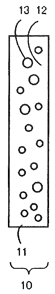
[0120]A polyethylene terephthalate pellet (manufactured by Bell Polyester Products, Inc., brand name: IFG8L, refractive index: 1.68) and 0.6% by mass of zirconium oxide (ZrO2) powder (median diameter of the primary particles: 11 nm, refractive index: 2.40) based on the PET pellet were mixed for 30 minutes in a tumbler mixer to obtain a PET pellet which ZrO2 powder was attached to its surface homogeneously. The obtained pellet was supplied to a hopper of a twin-screw kneading machine with a strand die and extruded at 250° C. to obtain a masterbatch in which the ZrO2 particles are kneaded in. The obtained masterbatch and the PET pellet (brand name: IFG8L) were mixed homogeneously in a proportion of 1:3, introduced into a hopper of a single-screw kneading machine with a T die, and extruded at 250° C. to produce a film in a thickness of 75 μm. The ZrO2 particles concentration in the film was 0.15% by mass. The film (the light diffusion layer) thickness t (μm) and the concentration c (% ...

example 2

[0123]A polycarbonate (PC) pellet (manufactured by Sumika Styron Polycarbonate Limited, brand name: SD2201W, refractive index: 1.59) and 0.01% by mass of zirconium oxide (ZrO2) powder (median diameter of the primary particles: 11 nm, refractive index: 2.40) based on the PC pellet were mixed for 30 minutes in a tumbler mixer to obtain a PC pellet which ZrO2 powder was attached to its surface homogeneously. The obtained pellet was supplied to a hopper of a twin-screw kneading machine with a strand die and extruded at 270° C. to obtain a PC pellet in which the ZrO2 particles are kneaded in. The obtained PC pellet (brand name: IFG8L) was used to produce a board-form molded article in a thickness of 3 mm (3000 μm) with an injection molding machine (Trade Name: FNX-III; manufactured by Nissei Plastic Industrial Co., Ltd.). The ZrO2 particles concentration in the board-like molded article was 0.01% by mass. The board-like molded article (the light diffusion layer) thickness t (μm) and the ...

example 3

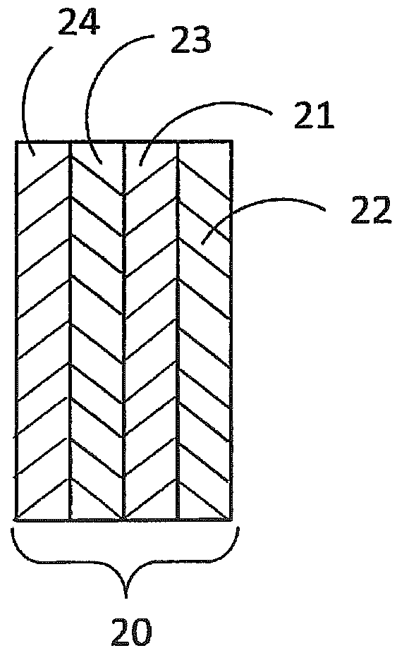
[0126]A PMMA pellet (manufactured by Mitsubishi Rayon Co., Ltd., trade name: ACRYPET VH, refractive index: 1.49) and 2.0% by mass of zirconium oxide (ZrO2) powder (median diameter of the primary particles: 11 nm, refractive index: 2.40) based on the PMMA pellet were mixed for 30 minutes in a tumbler mixer to obtain a PMMA pellet which ZrO2 powder was attached to its surface homogeneously. The obtained PMMA pellet was supplied to a hopper of a twin-screw kneading machine with a strand die and extruded at 250° C. to obtain a PMMA pellet in which the ZrO2 particles are kneaded in. The obtained PMMA pellet was dissolved in a toluene solution to obtain a polymer solution having a polymer concentration of 10% by mass. The obtained polymer solution was coated onto a transparent glass plate (3 mm thick) by using a doctor blade (manufactured by Eager Corporation). The polymer solution-coated glass plate was dried for 2 days at 60° C. on a hot plate to produce a transparent screen comprising ...


PUM

PropertyMeasurementUnit
median diameteraaaaaaaaaa
refractive index n2aaaaaaaaaa
reflectanceaaaaaaaaaa

Abstract

[Problem] Provided is a transparent screen which satisfies both the visibility of the projection light and the transmission light by anisotropically scattering and reflecting the projection light emitted from a light source.[Solving means] A transparent screen according to the present invention comprises a light diffusion layer including a binder and microparticles,said transparent screen having a scattered light brilliance profile characterized to meet the following conditions A to C:A: the emitted light relative brilliance in the 0° direction is from 50 to 95, when the entered light relative brilliance is 100;B: the emitted light relative brilliance in the ±5° direction is 1.1 or less, when the emitted light relative brilliance in the 0° direction is 100; andC: the emitted light relative brilliance in the ±50° direction is 0.0005 or higher, when the emitted light relative brilliance in the 0° direction is 100;when the brilliance is Y from the XYZ color system measured with a goniophotometer.

Description

TECHNICAL FIELD[0001]The present invention relates to a transparent screen which satisfies both the visibility of the projection light and the transmission light by anisotropically scattering and reflecting the projection light emitted from a light source. The present invention also relates to a video image projection system comprising the transparent screen and a projection device.BACKGROUND ART[0002]Conventionally, a combination of a Fresnel lens sheet and a lenticular lens sheet has been used for a projector screen. In recent years, a demand for displaying merchandise information, advertisement, or the like by projection on a show window of a department store or the like, a transparent partition of an event venue, or the like while maintaining the transparency thereof is growing. It is said that, in the future, a demand for a highly transparent projection type image display screen which is used for a head-up display, a wearable display, or the like will be further increasing.[000...

Claims


Application Information

Patent Timeline
Patent Type & Authority Applications(United States)
IPC IPC(8): G03B21/62G02B5/02E06B7/28
CPCG03B21/62G02B5/0242E06B7/28G03B21/00G02B5/0289H04N9/3194H04N5/74G02B5/02
Inventor YAMAKI, KOUSUKEMATSUO, AKIRANISHIMURA, SUZUSHI
Owner ENEOS CORP
Why Eureka
Try Eureka