
System and method for feedback-driven neuromodulation

a neuromodulation and feedback technology, applied in the field of neuromodulation, can solve the problems of inability to provide a system for simultaneous stimulation of the nervous system and signal reception, field and the technology and methods supporting it are in their infancy, and achieve the effects of improving current dbs devices, improving efficiency, and improving safety

Active Publication Date: 2018-07-05
RGT UNIV OF MINNESOTA
View PDF3 Cites 2 Cited by
  • Summary
  • Abstract
  • Description
  • Claims
  • Application Information

AI Technical Summary

Benefits of technology

The patent describes a system and method for using electromagnetic stimulation to treat brain disorders like deep brain stimulation. The system can use different waveforms and can detect the small signals from the nervous system even in the presence of large amounts of noise. It includes efficient detection and feedback loops to control the stimulation and improve the accuracy of the treatment. The technical effects include improved safety, efficiency, and simplification of the neurosurgical procedures.

Problems solved by technology

This field and the technology and methods supporting it however are in their infancy.
Currently, there is no system available for simultaneous stimulation of the nervous system and the signal reception.

Method used


Image

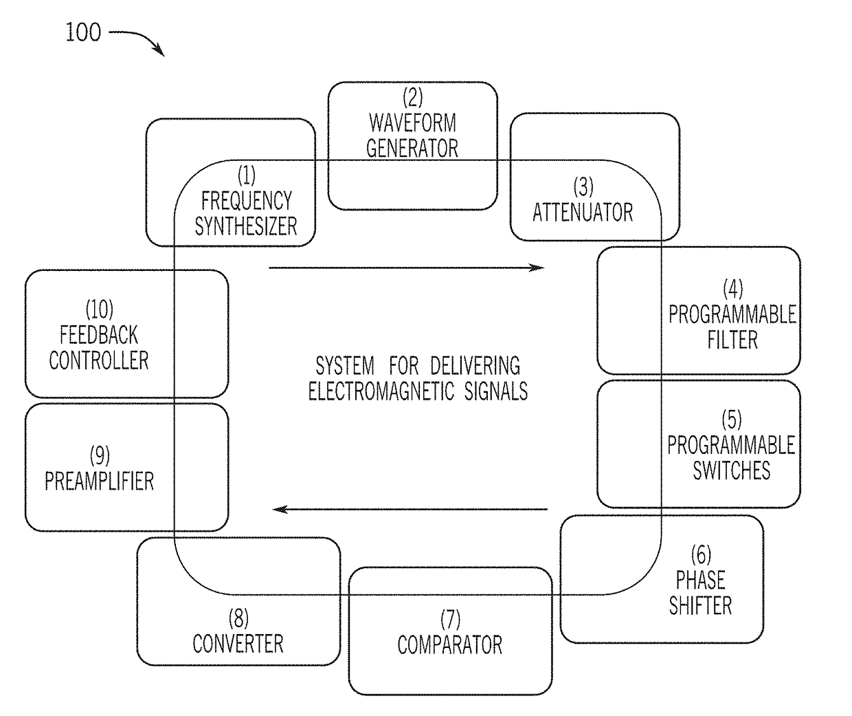
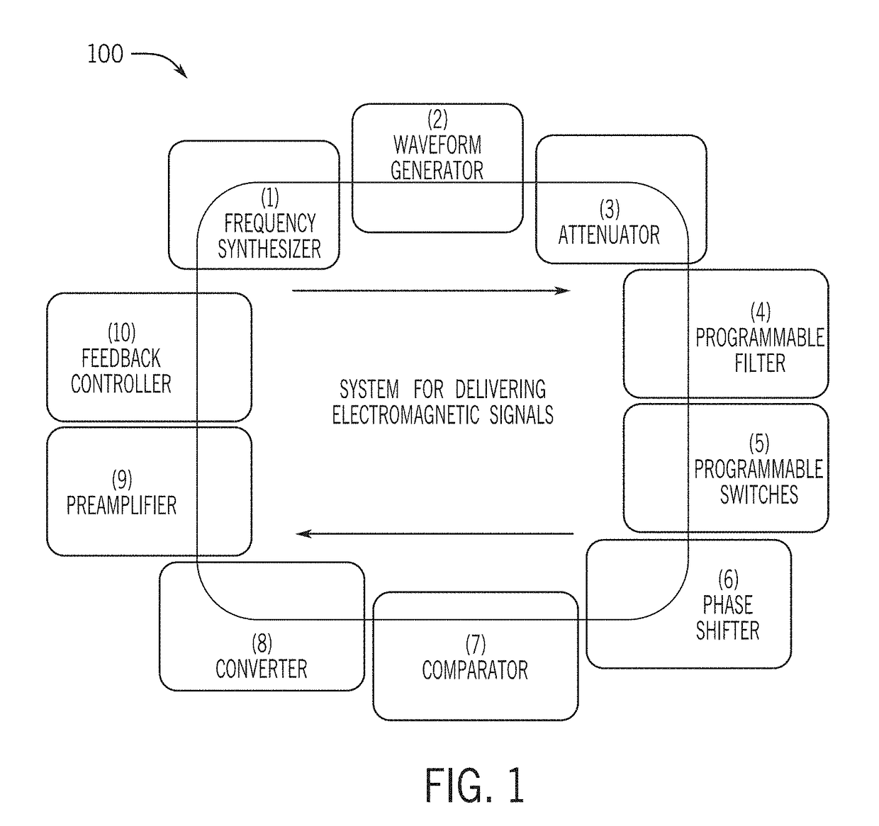
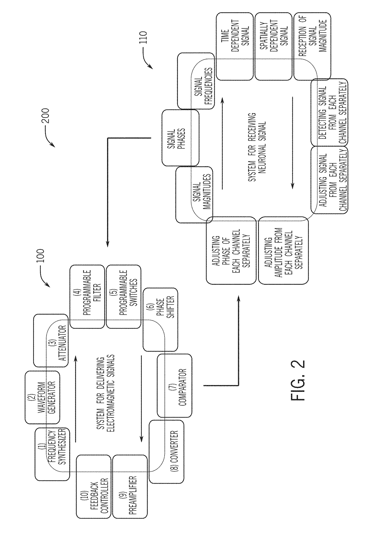
  • System and method for feedback-driven neuromodulation
  • System and method for feedback-driven neuromodulation
  • System and method for feedback-driven neuromodulation

Examples


example 1

[0055]Epidural electrical stimulation (EES) can facilitate non-voluntary motor activity and enable volitional control of motor functions loss because of the spinal cord injury (SCI). Specifically, the orientation of spinal cord dorsal structures, with respect to the electrical field, play a critical role in determining motor evoked potentials facilitated via EES. In one example, a swine model was used to investigate the relationship between spinal cord neuroanatomy and EES evoked motor responses due to the similarity to humans in terms of anatomical dimensions, size and orientation of the vertebral bone structures and spinal segments. The protocols for selective stimulation of the dorsal roots afferents were designed based on the anatomical measurements of the swine lumbar spinal cord. The differences between L5−L6 and L1−L4 segments were quantified in terms of spatial orientation of the dorsal roots. This protocol included stimulation with quadrupole electrode with sinusoid wavefor...

example 2

[0057]Pulse patterns used in deep brain stimulation (DBS) therapy are thought to induce largely non-specific axonal activation surrounding active electrodes. Given the proximity of active electrodes to regions implicated in side effects of DBS as well as the high levels of anisotropy within and surrounding DBS targets, more selective stimulation approaches allow for effective therapies, while minimizing undesired side effects. In some instances, as referenced above, a spatiotemporal approach based on

[0058]Rotating Field Phase Steering (RFPS) paradigms can be used enhancing orientation selectivity of axonal activation.

[0059]RFPS approaches were evaluated using computational tissue conductance models developed in COMSOL and coupled with axonal models in NEURON to estimate axon activation thresholds for (1) a Medtronic 4-annular-contact channel DBS lead and (2) an Abbott 8-contact array with two annular contacts separated by two rows of 3 segmented contacts. Stimulation was applied in ...


PUM


Abstract

Systems and methods are provided for neuromodulation with simultaneous stimulation and reception of neuronal response. A closed-loop control system provides the ability to modulate any combination of at least five parameters of stimulation (magnitude, frequency, amplitude, time, and phase) based on any combination of at least five parameters of received signals. The neuromodulation is well-suited for deep brain stimulation (DBS) applications.

Description

CROSS-REFERENCE TO RELATED APPLICATIONS[0001]The present disclosure is based on, claims priority to, and incorporates herein by reference in its entirety, U.S. Provisional Application Ser. No. 62 / 442,875, entitled, “SYSTEM AND METHOD FOR FEEDBACK-DRIVEN NEUROMODULATION,” filed Jan. 5, 2017.BACKGROUND[0002]The present disclosure relates generally to neuromodulation and, more particularly, to simultaneous stimulation and reception of neuronal response. A closed-loop control system may be provided with an ability to modulate any combination of multiple parameters of stimulation, for example, including magnitude, frequency, amplitude, time, and / or phase based on any combination of parameters of received signals.[0003]Neurostimulation by the introduction of exogenous electromagnetic signals by means of electrodes or wireless methods has demonstrated and delivered many scientific and therapeutic benefits. This field and the technology and methods supporting it however are in their infancy...

Claims


Application Information

Patent Timeline
IPC IPC(8): A61N1/36A61N1/05
CPCA61N1/36139A61N1/36062A61N1/0534A61N1/0551A61N1/36064A61N1/36067
Inventor MICHAELI, SHALOMVAUGHAN, JOHN T.MANGIA, SILVIALEHTO, LAURIJOHNSON, MATTHEWSLOPSEMA, JULIAGROHN, OLLIMOLNAR, GREGORY F.
Owner RGT UNIV OF MINNESOTA
Learn More