Check patentability & draft patents in minutes with Patsnap Eureka AI!

Single-Frame Autofocusing Using Multi-LED Illumination

a single-frame, autofocus technology, applied in the field of microscopy/imaging assemblies with single-frame sample autofocus, can solve the problems of damage to the sample photobleaching, poor image quality in digital pathology, autofocusing issues, etc., to reduce the time needed for autofocusing, maximize image contrast, and improve image quality

Active Publication Date: 2018-07-05
UNIV OF CONNECTICUT
View PDF0 Cites 18 Cited by
  • Summary
  • Abstract
  • Description
  • Claims
  • Application Information

AI Technical Summary

Benefits of technology

The present disclosure provides better imaging techniques, equipment and systems using a multi-LED approach for autofocusing. This approach offers advantages such as longer autofocusing ranges, more precise estimation of focal plane, and enhanced resolution of captured autofocus image. Compared to current practice, the present disclosure reduces the time needed for autofocusing and improves accuracy in estimating the focal plane. The multi-LED approach features an enhanced autofucing z-range and does not require z-scanning. Overall, the present disclosure offers more robust, easier to set-up, and more precise autofocus capabilities.

Problems solved by technology

A technical barrier for high-throughput WSI instruments is the time-consuming autofocusing process, which imposes a limit on the achievable throughput and may cause photobleaching damages to the samples.
Autofocusing issues have often been cited as the culprit for poor image quality in digital pathology, in particular for tissue sections with low image contrast.
This is generally not because autofocusing is difficult to do, but rather because of the typical need to perform accurate autofocusing at high speed.
However, this method can fail if a sample varies its location from the surface, such as with tissue slides.
This may be because the focus is maintained at a constant distance above the glass surface, and thus, it cannot track the sample topography variations above the surface.
Evident by its name, this method generally relies on the contrast of the sample and it can be difficult to handle transparent or low-contrast samples.
It is noted that focusing on every tile can be time-consuming.
Despite its application in current WSI systems, it is unclear whether the image-contrast-based method can be used for high-throughput fluorescence imaging, where samples are typically transparent under the bright-field illumination.
If one uses the fluorescence channel for autofocusing, it can be time-consuming to capture multiple fluorescence images under the low-light condition.
The sample may also be damaged due to the photo-bleaching effect.

Method used


Image

  • Single-Frame Autofocusing Using Multi-LED Illumination
  • Single-Frame Autofocusing Using Multi-LED Illumination
  • Single-Frame Autofocusing Using Multi-LED Illumination

Examples


example 1

Single-Frame Sample Autofocusing Using Multi-LED Illumination

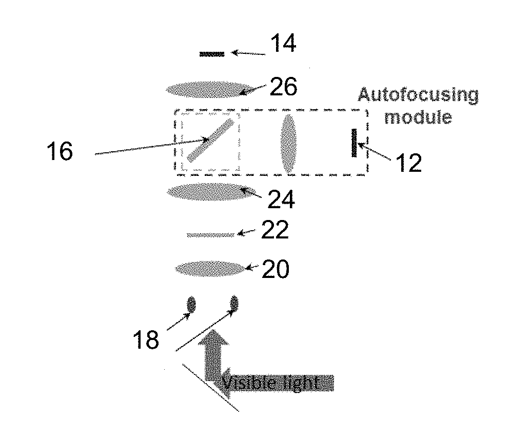
[0062]In exemplary embodiments, the present disclosure provides a new and advantageous autofocusing assembly / method using only one captured image, as shown in FIG. 2.

[0063]As shown in FIG. 2, one can position (or use a lens to relay) two or more LEDs (e.g., two or more infrared LEDs) to the back focal plane of the condenser lens 20 (e.g., condenser lens of a microscope or the like).

[0064]Therefore, these two or more LEDs 18 are configured and adapted to illuminate the sample 22 from two or more different incident angles.

[0065]At the detection path, one can position a mirror 16 (e.g., a 45-degree hot mirror) to reflect the infrared light from the two or more infrared LEDs to the autofocusing image sensor / camera 12 (e.g., autofocusing image sensor / camera 12 within the autofocusing module).

[0066]In exemplary embodiments, it is noted that regular visible light remains unchanged and can be detected by the image sensor / camera 14...

example 2

Multi-LED Illumination Scheme for Autofocusing

[0091]In an exemplary embodiment, the present disclosure provides a new and advantageous autofocusing assembly / method using one captured image, as shown in FIG. 6. FIG. 6A depicts an exemplary implementation scheme and FIG. 6B depicts an experimental prototype setup. The disclosed embodiment requires no axial scanning and no additional camera and / or lens. Indeed, the disclosed embodiment provides effective results for stained and transparent samples, and allows continuous sample motion in the surveying process.

[0092]As shown in FIG. 6A, two or more LEDs are positioned in the illumination path at the back focal plane of the condenser lens to simultaneously illuminate the sample with two or more different oblique incident angles. The LEDs can be partially coherent light sources and generate coherent contrast for samples at an out-of-focus region.

[0093]In an exemplary embodiment, the LEDs include a white surface mounted LED 28 and at least ...

example 3

Multi-LED Illumination Scheme for Autofocusing in a Time-Lapse

[0107]In an exemplary embodiment, Example 2 is modified to correct the focal position of the sample in a time-lapse experiment. In this case, the method includes (i) moving the sample to an offset position, (ii) activating the multiple LEDs and capturing the image for autofocusing purposes, (iii) performing autocorrelation analysis and recovering the focus position from the locations of the first-order peaks, and (iv) moving the sample to an in-focus position.


PUM


Abstract

Instruments, assemblies and methods are provided for undertaking imaging techniques (e.g., microscopic imaging techniques). The present disclosure provides improved imaging techniques, equipment and systems. More particularly, the present disclosure provides advantageous microscopy / imaging assemblies with single-frame sample autofocusing using multi-LED illumination. The present disclosure provides for assemblies and methods for single-frame rapid sample autofocusing without a z-scan. Potential applications for the disclosed assemblies / methods include, without limitation, whole slide imaging, optical metrology, wafer inspection, DNA sequencing and other high-throughput imaging applications where the sample may need to be scanned over a large field of view. The assemblies / methods advantageously utilize multiple LEDs for sample illumination. A captured image includes multiple copies of the sample, and one can recover the distance between these copies. The distance is directly related to the defocus distance.

Description

CROSS-REFERENCE TO RELATED APPLICATIONS[0001]The present application claims priority benefit to U.S. Provisional Patent Application No. 62 / 441,727, entitled “Single-Frame Autofocusing using Multi-LED Illumination,” which was filed on Jan. 3, 2017. The content of the foregoing provisional application is hereby incorporated by reference.STATEMENT OF GOVERNMENT SUPPORT[0002]This invention was made with Government support under Grant 1555986 awarded by the National Science Foundation. The government has certain rights in the invention.FIELD OF THE DISCLOSURE[0003]The present disclosure relates generally to the field of imaging techniques, equipment and systems and, more particularly, to microscopy / imaging assemblies with single-frame sample autofocusing using multi-light-emitting diode (“multi-LED”) illumination.BACKGROUND OF THE DISCLOSURE[0004]In general, high-density solid-state detector technology, coupled with affordable, terabyte-scale data storage, has greatly facilitated the dev...

Claims


Application Information

Patent Timeline
IPC IPC(8): H04N5/232G06T3/20H04N5/225H04N5/33G06T7/70G06N3/04G02B21/06G02B21/36
CPCH04N5/23212G06T3/20H04N5/2256H04N5/33G06T7/70G06N3/04G02B21/06G02B21/361G02B21/362G02B21/365G06T2207/20081G06T2207/10048G06T2207/10056H04N5/2253G02B21/02G02B21/244G02B21/245G02B7/365G06N3/08H04N23/56H04N23/671G06N3/045H04N23/20H04N23/54
Inventor ZHENG, GUOAN
Owner UNIV OF CONNECTICUT
Features
  • R&D
  • Intellectual Property
  • Life Sciences
  • Materials
  • Tech Scout
  • Unparalleled Data Quality
  • Higher Quality Content
  • 60% Fewer Hallucinations
Learn More