Energy Storage Systems

a technology of energy storage and energy storage, applied in the field of energy storage systems, can solve the problems of affecting the efficiency of the prior art system, the cost of running, and the inability to meet the needs of the environment, and achieve the effects of reducing the use of additional pumping, and reducing the cost of operation

Active Publication Date: 2018-07-12
SUNAMP
View PDF0 Cites 22 Cited by
  • Summary
  • Abstract
  • Description
  • Claims
  • Application Information

AI Technical Summary

Benefits of technology

[0041]In preferred embodiments, at least one or all of the phase transitions may be reversible without substantial loss of energy absorbing and / or storing and / or releasing capacity across at least more than one reversible cycle or cycles.
[0425]69. Many embodiments include all or some of pumps, compressors, thermoelectric devices, powered valves, control electronics and power electronics (or other powered components that dissipate waste heat in their operation). All or most of these components require cooling to avoid failure or degraded performance. In preferred embodiments directing the waste heat from these components to one or more suitable melting point banks of PCM provides such cooling, thereby harnessing (for later use) rather than wasting the “waste heat”. Generally such components are air-cooled. In a preferred embodiment all components to be air-cooled are located in a sealed void, e.g. a chamber 100 mm front to back, as wide and high as the Thermal Store, mounted on the front side of the Thermal Store behind a sealed door (capable of being opened for servicing, but normally forming an air-tight seal). Within this chamber an air-to-water radiator is mounted near the top of the chamber, relying on convection and / or fan-assisted airflow to draw air warmed by the components through the radiator. (A return path for cooled air to return to the bottom of the chamber is provided.) The HTF flowing in the water side of the radiator is chosen to flow to a bank or banks (in succession) having PCM with melting point temperatures (e.g. 24° C.) low enough to cool the air in the chamber to a suitable temperature to, in turn, cool the components and keep them at acceptable operating temperatures. Apart from capturing as useful heat the waste heat from the operation of these components, it also reduces or eliminates a number of the unwanted side effects from standard open loop approaches to air cooling:

Problems solved by technology

Although there are many heating and cooling systems on the market many of these prior art systems suffer from efficiency problems and are also expensive to run.
Prior art systems also tend to be based on fossil fuels which are environmentally unfriendly.
So going back to the original fuel, electric heating is only around 30% efficient.
As a result we face major problems in continuing to use these fossil fuels:They will run out within foreseeable timeframes (ranging from decades for oil to centuries for gas and coal).
The consequence is climate change with potentially catastrophic consequences in loss of both planetary biodiversity and human habitat (water shortages, desertification, and sea level rise).
They are therefore only really suited to generating grid electricity.Wind turbines harness winds which originate from solar energy driving the movement of air masses.
Except in very few parts of the world, hydro cannot provide the bulk of the demand for grid electricity.
There are limited further sites to implement large reservoirs, and there can be human and bio-diversity issues around flooding large areas.Wave power uses waves which are largely generated by action of the wind on the sea.
However there are major concerns about competition between food and bio-fuel crop production, and between bio-fuel crops and naturally bio-diverse land (e.g. the elimination of jungle for palm oil).
It can be observed that apart from biofuels and some hydro, solar-driven renewables energy conversion devices do not operate on-demand (or in the jargon of the electricity generating industry, they are not “dispatchable”): their energy comes when the sun shines; when the wind blows; when seas are high.
Storing electrical energy is difficult.
This process is 90% efficient, but suitable pumped-storage hydro sites are scarce.
The liquid—gas phase change material is usually not practical for use as thermal storage due to the large volumes or high pressures required to store the materials when in their gas phase.
However, there are a number of problems with practical use of phase change materials including achieving suitable rates of heat transfer in and out and acceptable levels of thermodynamic efficiency.

Method used


Image

  • Energy Storage Systems
  • Energy Storage Systems
  • Energy Storage Systems

Examples


Embodiment Construction

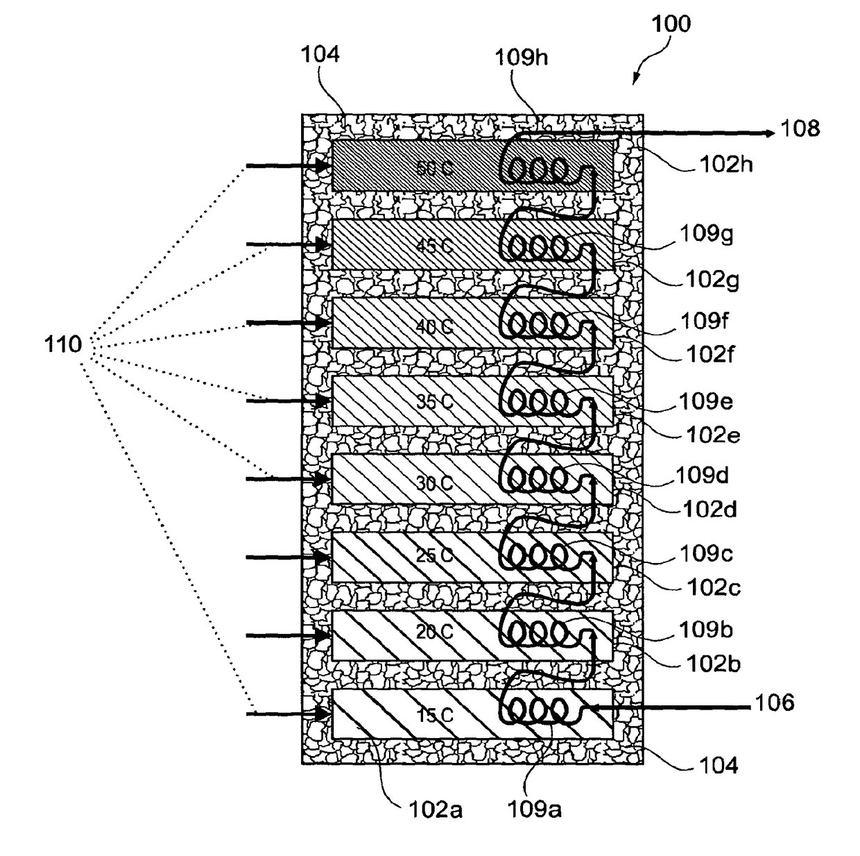
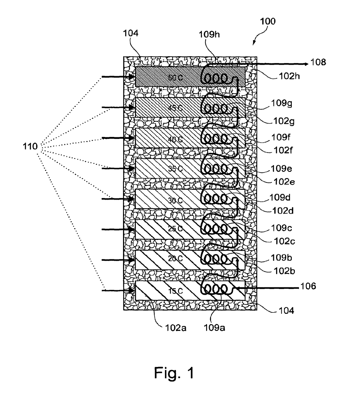
[0488]FIG. 1 is a representation of an energy storage system according to the present invention generally designated 100. The heating / cooling system comprises a series and / or a collection of banks 102a, 102b, 102c, 102d, 102e, 102f, 102g and 102h which are used to collect and store thermal energy from, for example, a solar thermal panel (not shown) and, for example, later deliver thermal energy to heat up cool water. Although FIG. 1 shows eight banks, the invention is intended to cover any suitable number of banks. Each of the banks 102a, 102b, 102c, 102d, 102e, 102f, 102g, 102h contains a different phase change material which therefore has a different melting point to store heat. As shown in FIG. 1, there is insulation 104 around the banks 102a, 102b, 102c, 102d, 102e, 102f, 102g, 102h. Bank 102a is at temperature of about 15° C. by virtue of containing a suitable phase change material with a phase transition temperature of 15° C. Similarly, bank 102b is at temperature of about 20°...


PUM

PropertyMeasurementUnit
temperatureaaaaaaaaaa
temperaturesaaaaaaaaaa

Abstract

There is herein described energy storage systems. More particularly, there is herein described thermal energy storage systems and use of energy storable material such as phase change material in the provision of heating and / or cooling systems in, for example, domestic dwellings.

Description

CROSS-REFERENCE TO RELATED APPLICATIONS[0001]This patent application is a continuation application of and claims benefit of the filing date of copending U.S. application Ser. No. 13 / 509,979 entitled “Energy Storage Systems” filed May 16, 2012, which is a US National Stage Entry of PCT / GB2010 / 051910 entitled “Energy Storage Systems” filed Nov. 16, 2010, and which claims foreign priority to United Kingdom application GB 0919934.0 entitled “Energy Storage Systems” filed Nov. 16, 2009.FIELD OF THE INVENTION[0002]This invention relates to energy storage systems. More particularly, the present invention relates to thermal energy storage systems and use of energy storable material such as phase change material in the provision of heating and / or cooling systems in, for example, domestic dwellings.INCORPORATION BY REFERENCE[0003]This patent application incorporates by reference in its entirety copending U.S. application Ser. No. 13 / 509,979 entitled “Energy Storage Systems” filed May 16, 2012...

Claims


Application Information

Patent Timeline
Patent Type & Authority Applications(United States)
IPC IPC(8): F24D11/00F24D11/02F24H9/20F28D20/02F24H7/04F24D18/00F24S10/40F24S10/95
CPCF28D20/02Y02B30/125Y02B30/52Y02E10/44Y02B10/22Y02E60/145Y02B10/70Y02B10/40F28D20/021F24H2240/08F24H9/2014F24H9/20F24H7/0441F24H7/04F24D2200/20F24D2200/16F24D2200/14F24D2200/12F24D2200/11F24D11/0214F24D11/004F24D11/003Y10T29/4935F24S10/45F24D2220/10F24S60/10F24S10/95Y02B10/20Y02E60/14F24D2101/40F24D2103/13F24D18/00F24D2101/30F24D2103/20F24D2103/17F24D2101/10F24D2101/70F24D2101/80F24S10/90F24S60/00F24H2250/00Y02B30/12F28D1/0426F28D20/0039F28D20/026F28D20/028F28D2020/0013F28D2020/0026F28D2020/0078F28D2020/0082
Inventor FIELD, JOHNBISSELL, ANDREW
Owner SUNAMP
Why Eureka
Try Eureka