Data processing device

a data processing and data technology, applied in image data processing, image enhancement, instruments, etc., can solve the problems of large amount of data collected in imaging mass microscopes, inability to provide useful information for analysis operators, and inability to use multivariate analysis in the previously described manner. to achieve the effect of easy identification and accurate identification

Active Publication Date: 2018-07-12
SHIMADZU CORP
View PDF0 Cites 17 Cited by
  • Summary
  • Abstract
  • Description
  • Claims
  • Application Information

AI Technical Summary

Benefits of technology

[0043]With the data processing device according to the present invention, useful information on a sample can be collected for identifying a substance contained in the sample, grasping the two-dimensional distribution of the substance, and determining the quantity of the identified substance. Specifically, for example, the data processing device according to the present invention conveniently allows for an investigation of the mass-to-charge ratio of a substance singularly present at a site or area having a color which the analysis operator is focusing on in an optical microscopic image, whereby the substance showing a two-dimensional distribution which the analysis operator is focusing on can be easily and accurately identified.

Problems solved by technology

However, since the amount of data collected in an imaging mass microscope is extremely large, a considerable amount of time and labor is required to locate a mass-to-charge ratio at which the mass spectrometric imaging graphic provides significant information.
However, using a multivariate analysis in the previously described manner does not always provide useful information for an analysis operator.
Such a task is extremely cumbersome.

Method used


Image

  • Data processing device
  • Data processing device
  • Data processing device

Examples


first embodiment

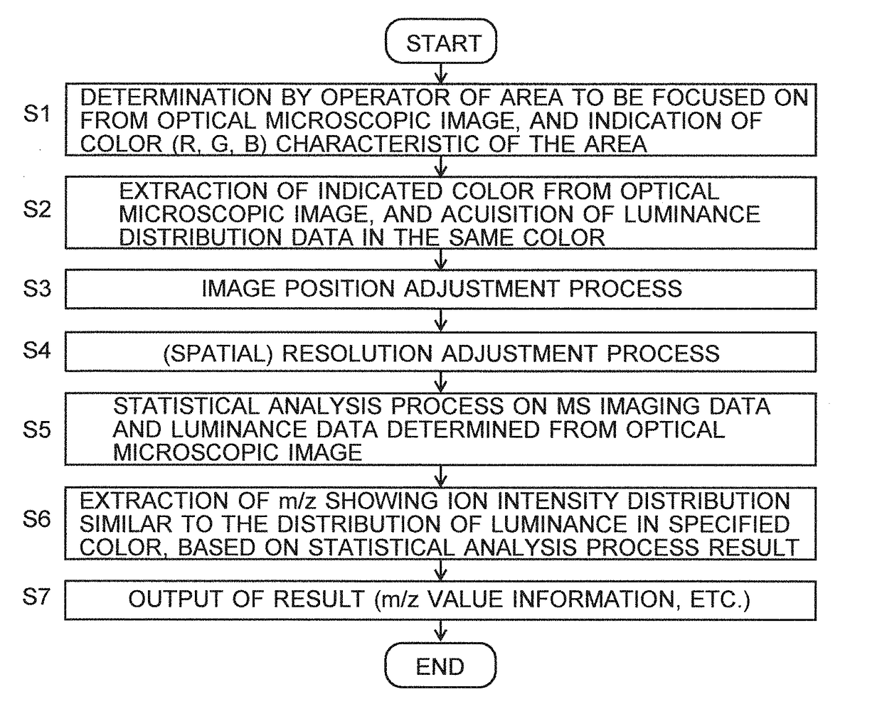
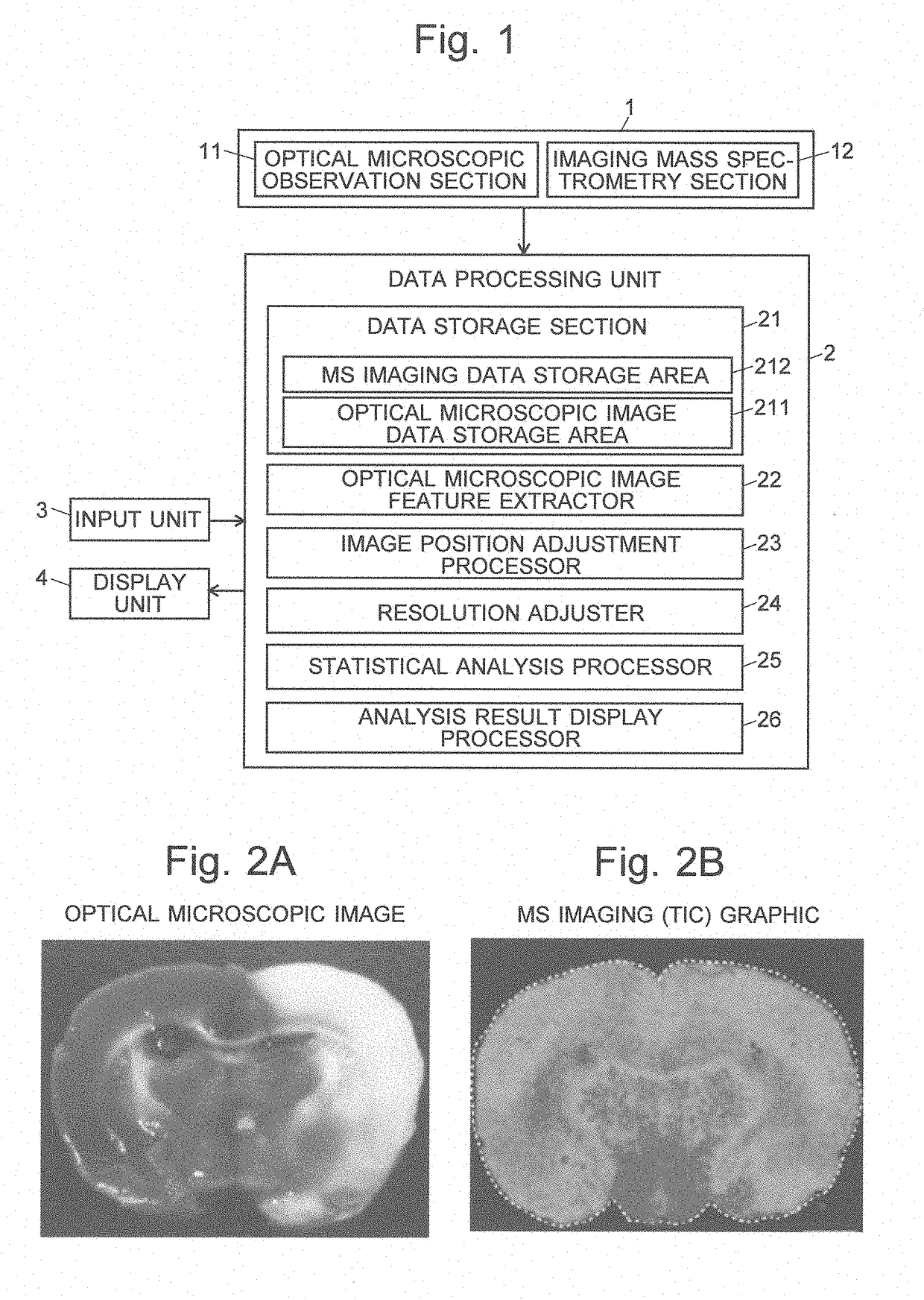
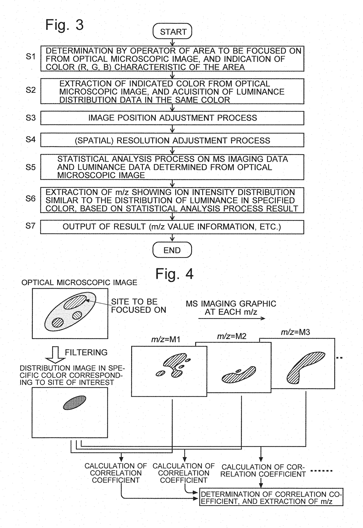
[0060]FIG. 1 is a schematic configuration diagram of the first embodiment of an imaging mass microscope system using a data processing device according to the present invention.

[0061]This system includes an imaging mass microscope main unit 1 and a data processing unit 2.

[0062]The imaging mass microscope main unit 1 includes: an optical microscopic observation section 11 for obtaining an optical microscopic observation image of a two-dimensional area on a sample; and an imaging mass spectrometry section 12 for performing a mass spectrometric analysis over a predetermined range of mass-to-charge ratios for each of the micro areas formed by subdividing a predetermined two-dimensional area on the same sample, to collect mass spectrum data for each micro area.

[0063]The data processing unit 2 includes the following functional blocks: a data storage section 21, which has an optical microscopic image data storage area 211 for storing optical microscopic image data and an MS imaging data st...

second embodiment

[0085]As described earlier, in the first embodiment, a luminance distribution image in a specific color is extracted from an optical microscopic image which is a colored image. The data forming this luminance distribution image are two-dimensional data, while the original optical microscopic image, which has the luminance distribution for each of the RGB colors (i.e. for each wavelength), is three-dimensional data including the color or wavelength as one of the parameters. Therefore, the system can be configured to perform a statistical analysis process using a multivariable analysis (such as the PLS) on a matrix obtained from each set of the data forming the optical microscopic image (i.e. the luminance distribution data for each of the different colors of RGB) as well as a matrix obtained from mass spectrometric imaging data at each mass-to-charge ratio, to extract a combination of a color or wavelength and a mass-to-charge ratio which show similar distributions.

[0086]In this conf...

third embodiment

[0087]FIG. 6 is a schematic configuration diagram of the third embodiment of an imaging mass microscope system using a data processing device according to the present invention. FIG. 7 is a model diagram for explaining the data processing operation in the imaging mass microscope system according to the third embodiment. In FIG. 6, the same components as used in FIG. 1 illustrating the first embodiment are denoted by the same numerals.

[0088]The data processing unit 2 in the present system includes the following functional blocks: an MS imaging data storage section 220 for storing mass spectrometric imaging data; a compound database 221 in which mass spectra (which include MSn spectra) for various known kinds of compounds are registered; a reference spectrum selector 222; a statistical analysis processor 223; and a correlation coefficient distribution image creator 224.

[0089]The imaging mass spectrometry section 12 in the imaging mass microscope main unit 1 performs mass spectrometric...


PUM


Abstract

An analysis operator checks an optical microscopic image obtained with an imaging mass microscope and indicates a color characteristic of an area which the analysis operator is focusing on. An optical microscopic image feature extractor calculates luminance distribution data in the indicated color. An image position adjustment processor performs a position adjustment process on a luminance distribution image derived from the optical microscopic image and an MS imaging graphic, while a resolution adjuster equalizes their spatial resolutions. A statistical analysis processor calculates a coefficient of spatial correlation between the luminance distribution image and the MS imaging graphic for each mass-to-charge ratio. Based on the calculated correlation coefficients, an analysis result display processor extracts a mass-to-charge ratio which shows an ion intensity distribution similar to the luminance distribution image. and displays it on a display unit.

Description

TECHNICAL FIELD[0001]The present invention relates to a data processing device for processing data obtained by performing a measurement or observation on a sample or specimen, and more specifically, to a data processing device suitable for acquiring significant information on a sample by processing a plurality of sets of multi-dimensional analysis data (e.g. two-dimensional or three-dimensional data) obtained by different measurement techniques or observation techniques for the same sample.BACKGROUND ART[0002]Various devices for performing a predetermined measurement or analysis on a sample or specimen to collect data representing a two-dimensional distribution of a predetermined physical quantity for the sample have been commonly known.[0003]For example, an imaging mass microscope disclosed in Non Patent Literature 1 or other documents allows for an observation of the shape and state of the surface of a biological sample or similar specimen through an optical microscope while perfo...

Claims


Application Information

Patent Timeline
Patent Type & Authority Applications(United States)
IPC IPC(8): H01J49/00G06K9/62G06T7/00G06F17/18G06V10/56G16B40/10G16B40/30
CPCH01J49/0036G06K9/6206G06T7/97G06F17/18G06T2207/10056G01N33/483G16B40/00G16B40/30G16B40/10G06V20/69G06V10/56
Inventor YAMAGUCHI, SHINICHI
Owner SHIMADZU CORP
Why Eureka
Try Eureka