Supercharge Your Innovation With Domain-Expert AI Agents!

Clc process and installation with the production of high purity nitrogen

a high-purity nitrogen, clc technology, applied in the direction of nitrogen purification/separation, combustion types, lighting and heating apparatuses, etc., can solve the problems of limited oxidation of solid oxygen transporters, inability to envisage implementation mode, and high investment and energy costs of supplemental steps carried out outside the chemical loop of gas before or after passing through the air reactor, so as to achieve a high yield and minimize production costs. , the effect of high nitrogen

Active Publication Date: 2018-07-26
INST FR DU PETROLE +2
View PDF1 Cites 2 Cited by
  • Summary
  • Abstract
  • Description
  • Claims
  • Application Information

AI Technical Summary

Benefits of technology

The aim of this patent is to provide a way to make high purity nitrogen gas, especially when total combustion is desired, in a good yield while minimizing costs.

Problems solved by technology

However, this condition is incompatible with the production of a high purity stream of nitrogen in a single pass as is conventionally carried out in a CLC process.
In this case, only partial oxidation of the hydrocarbon feed is desired in order to produce the syngas and oxidation of the solid oxygen transporter is limited as a result.
However, this implementational mode cannot be envisaged when total combustion of the hydrocarbon feed is desired, because oxidation of the active mass transporting the oxygen must be substantial in order to limit the quantity of active mass employed.
However, irrespective of the separation technology employed, such a supplemental step carried out outside the chemical loop on the gas before or after passing it through the air reactor is expensive in terms of investment and energy costs.
Furthermore, it is not demonstrated how a content of less than 10 ppm could be obtained without a supplemental purification step.
However, in that CLC configuration, the production of nitrogen is limited because the first step is carried out with air which contains a very large quantity of oxygen to be removed (almost 21% by volume of oxygen).

Method used


Image

  • Clc process and installation with the production of high purity nitrogen
  • Clc process and installation with the production of high purity nitrogen
  • Clc process and installation with the production of high purity nitrogen

Examples


example

[0134]The example below is intended to illustrate some of the advantages of the present invention.

[0135]Consider a CLC thermal power plant with a nominal output of 1000 MWth. The hydrocarbon feed in this example was a South African coal with the typical composition shown in Table 2 below.

TABLE 2ElementContent (%)Ash15.1C70.7H4.3O7.7N1.3S0.9

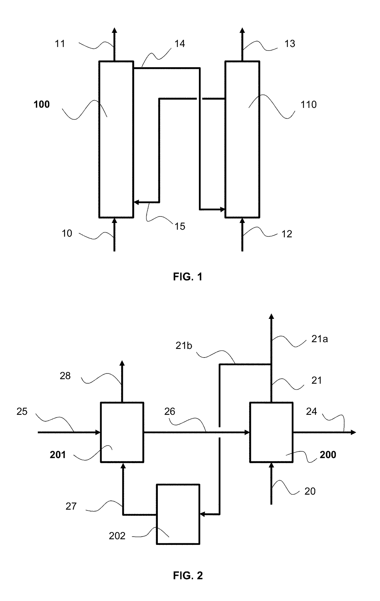
[0136]The CLC unit comprised two air reactors to carry out oxidation of the redox active mass, as described in relation to FIG. 2.

[0137]The flow rate of air necessary for total combustion of this feed was 290 Nm3 / s assuming a super-stoichiometry of 10%.

[0138]In simplified manner, the air was composed of 21% of oxygen and 79% of nitrogen.

[0139]This flow rate of air was supplied to the second air reactor 200 in order to oxidize the oxygen carrier. The stream of depleted air obtained from the second air reactor contained 2% of O2. The fraction of depleted air which was recycled and brought into contact with the particles of oxygen carrier in the firs...


PUM


Abstract

The invention concerns a CLC process, and its installation, producing high purity dinitrogen, comprising:(a) the combustion of a hydrocarbon feed by reduction of a redox active mass brought into contact with the feed,(b) a first step for oxidation of the reduced active mass (25) obtained from step (a) in contact with a fraction of a depleted air stream (21b), in order to produce a high purity stream of dinitrogen (28) and a stream of partially re-oxidized active mass (26);(c) a second step for oxidation of the stream of active mass (26) in contact with air (20) in order to produce a stream of depleted air and a stream of re-oxidized active mass (24) for use in step (a);(d) dividing the stream of depleted air obtained at the end of step (c) in order to form the fraction of depleted air used in step (b) and a fraction complementary to the depleted air extracted from the CLC.

Description

FIELD OF THE INVENTION[0001]The present invention relates to the field of the combustion of hydrocarbon feeds by chemical looping combustion (CLC), and more particularly to the production of nitrogen in the CLC.GENERAL CONTEXT[0002]Chemical Looping Combustion (CLC) is a process consisting of carrying out redox reactions on an active mass, typically a metal oxide, to break up the combustion reaction into two successive reactions: a first reaction for oxidation of the active mass in contact with an oxidizing gas, typically air, and a second reaction for reduction of the active mass in contact with the feed, the combustion of which is to be carried out. The CLC process resembles oxycombustion, with the principal difference being that the combustion is not supplied with a pure dedicated stream of oxygen as in the case of oxycombustion, but by the redoxing active mass acting as the transporter of the oxygen. This solid material is in the form of particles which are transported pneumatica...

Claims


Application Information

Patent Timeline
IPC IPC(8): B01J8/38F23C10/00F23C10/01F23C10/08C01B21/04B01J8/00B01J8/26
CPCB01J8/388F23C10/005F23C10/01F23C10/08C01B21/0416B01J8/0055B01J8/26F23C2900/99008B01J2208/00115F23C6/04F23C10/10F23J2217/40Y02E20/34F23C10/00
Inventor GUILLOU, FLORENTBERTHOLIN, STEPHANEYAZDANPANAH, MAHDI
Owner INST FR DU PETROLE
Features
  • R&D
  • Intellectual Property
  • Life Sciences
  • Materials
  • Tech Scout
  • Unparalleled Data Quality
  • Higher Quality Content
  • 60% Fewer Hallucinations
Learn More