
Metal PCB, headlight module having metal PCB applied thereto, and method for assembling headlight module

Active Publication Date: 2018-07-26
ECOCAB
View PDF2 Cites 10 Cited by
  • Summary
  • Abstract
  • Description
  • Claims
  • Application Information

AI Technical Summary

Benefits of technology

The present invention is able to create various illuminations by integrating LED chips, transfer heat well, and allow for different forms of fabrication. Additionally, the invention allows for quick coupling of metal PCBs to back plates, minimizes damage to the metal PCB, enables accurate control of the mounting angle, simplifies assembly, allows for simultaneous bending and mounting, and makes it easy to either mount or detach the metal PCB. These technical effects improve the performance and efficiency of LED chip arrays.

Problems solved by technology

However, such a metal PCB assembly for a vehicle lamp has disadvantages in that it has a configuration in which the unit pattern is bent, the unit patterns must be spaced apart in forming the external three faces for bending and it is difficult to mount the LED chips at a desired degree of integration.
However, such an LED lamp module has disadvantages in that heat-dissipation efficiency is low because the area of the heat sink 210 is limited and an assembly time and cost are increased because the separate heat sinks 210 are connected to the printed circuit board 200.
However, such a metal PCB assembly for a vehicle lamp has disadvantages in that it has a configuration in which the unit patterns are bent, the unit patterns must be spaced apart from each other in forming the external three faces for bending and it is difficult to mount the LED chips at a desired degree of integration.
However, such a metal printed circuit board has a disadvantage in that it has a configuration also serving as a light guide plate and cannot be easily applied to a polygonal or multi-directional structure and it has a difficulty in its application because the LED chips radiate light in different directions when the metal printed circuit board is bent.

Method used


Image

  • Metal PCB, headlight module having metal PCB applied thereto, and method for assembling headlight module
  • Metal PCB, headlight module having metal PCB applied thereto, and method for assembling headlight module
  • Metal PCB, headlight module having metal PCB applied thereto, and method for assembling headlight module

Examples


Embodiment Construction

[0130]The operation of the present invention configured as described above is described.

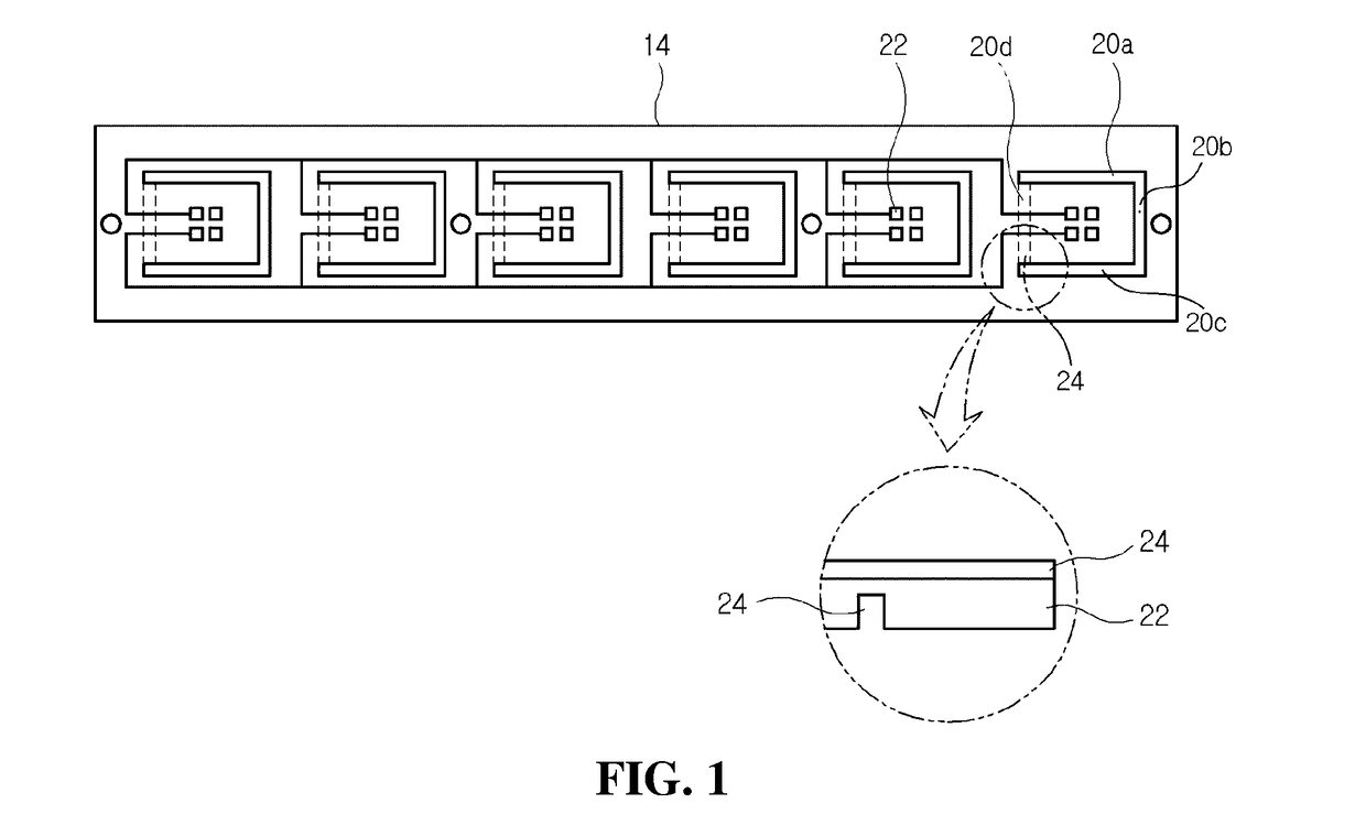
[0131]As shown in FIGS. 5 to 22, the metal PCB 500 of the present invention has a configuration in which a thermal conductor of a sheet form made of aluminum or copper and the patterns for mounting the LED chips 550 thereon have been integrated. The metal PCB enables heat, discharged by the LED chips 550, to be easily discharged through the thermal conductor.

[0132]Furthermore, the metal PCB 500 includes the plurality of chip mounting parts 530 formed to have independent forms on one side of the base 501. The base 501 is bent in the state in which the mounting parts 530 have been fixed so that the mounting parts 530 remain parallel.

[0133]In this case, the two or more LED chips 550 are mounted on the mounting part 530 in order to solve a problem in that a reduction in the degree of integration generated when each LED chip is mounted on a conventional unit pattern is generated.

[0134]That is, when th...


PUM


Abstract

Provided are a metal PCB, a headlight module having the metal PCB applied thereto, and a method for assembling the headlight module, wherein the metal PCB has a base made of a metal material and configured as a thin plate, or the base has a predetermined thickness and is bent in a desired direction through a bending groove formed on the rear surface thereof, and the base has a plurality of chip mounting portions integrated thereon such that one or more LED chips are mounted thereon, the chip mounting portions being spaced at a predetermined interval and having at least two parts of incision surfaces formed on one side of the base such that the chip mounting portions are inclined and installed to have a predetermined angle with regard to the base.

Description

TECHNICAL FIELD[0001]The present invention relates to a metal PCB, including a base of a metal material which is formed of a thin plate or has a specific thickness and is bent in a desired direction through bending grooves provided in a back surface, wherein cut faces of at least two parts are formed on one side of the base, spaced apart from one each other at a specific interval, disposed to be inclined at a specific angle to the base, and integrated with a plurality of chip mounting parts on which one or more LED chips are mounted, a headlight module to which the metal PCB is applied, and a method of assembling the headlight module.BACKGROUND ART[0002]In general, a printed circuit board (PCB) refers to a wiring board on which electronic parts are mounted to electrically connect parts or signal lines.[0003]Furthermore, the PCB is completed by compressing a copper foil against one side or both sides of an insulating plate, such as phenol resin and epoxy resin, forming a conductive p...

Claims


Application Information

Patent Timeline
IPC IPC(8): F21S41/19H01L25/075H01L33/62H01L33/64H01L23/538F21S41/141F21V29/503F21S45/47F21V29/89
CPCF21S41/192H01L25/0753H01L33/62H01L33/641H01L33/647H01L23/5387F21S41/141F21V29/503F21S45/47F21V29/89H01L2933/0066H01L2933/0075F21Y2115/10F21S41/151F21S43/14F21S43/195H01L33/64H05K1/0284H05K1/05H05K1/181H05K1/189H05K3/0061H05K2201/09054H05K2201/09063H05K2201/091H05K2201/10106H05K1/02H05K1/18
Inventor KIM, CHANG-WON
Owner ECOCAB
Learn More