Image generating apparatus and image generating method
Active Publication Date: 2018-07-26
PANASONIC INTELLECTUAL PROPERTY MANAGEMENT CO LTD
View PDF0 Cites 21 Cited by
Summary
Abstract
Description
Claims
Application Information
AI Technical Summary
This helps you quickly interpret patents by identifying the three key elements:
Problems solved by technology
Method used
Benefits of technology
Benefits of technology
The patent describes an improved apparatus and method for generating images that allows for easier understanding of materials. The apparatus is less bulky compared to previous methods and can be combined with a lensless microscope and digital micro-mirror device for light and dark inversion. The technical effects of the patent are improved image quality and simplified material analysis.
However, a problem with the method of Japanese Patent No. 5403458 is that the apparatus becomes more bulky.
However, if one attempts to extend the light and dark pattern over the entire image sensor, a lens becomes necessary, and the apparatus becomes more bulky.
When taking images while changing the positions of the light source and the digital micro-mirror device, since the apparatus is bulky, it is difficult to combine a lensless microscope with light and dark inversion by the digital micro-mirror device.
Method used
Image
Click on the blue label to locate the original text in one second.
Reading with bidirectional positioning of images and text.
Examples
embodiment 1
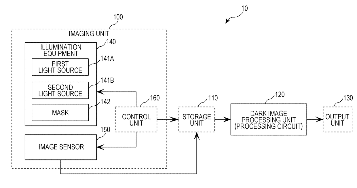
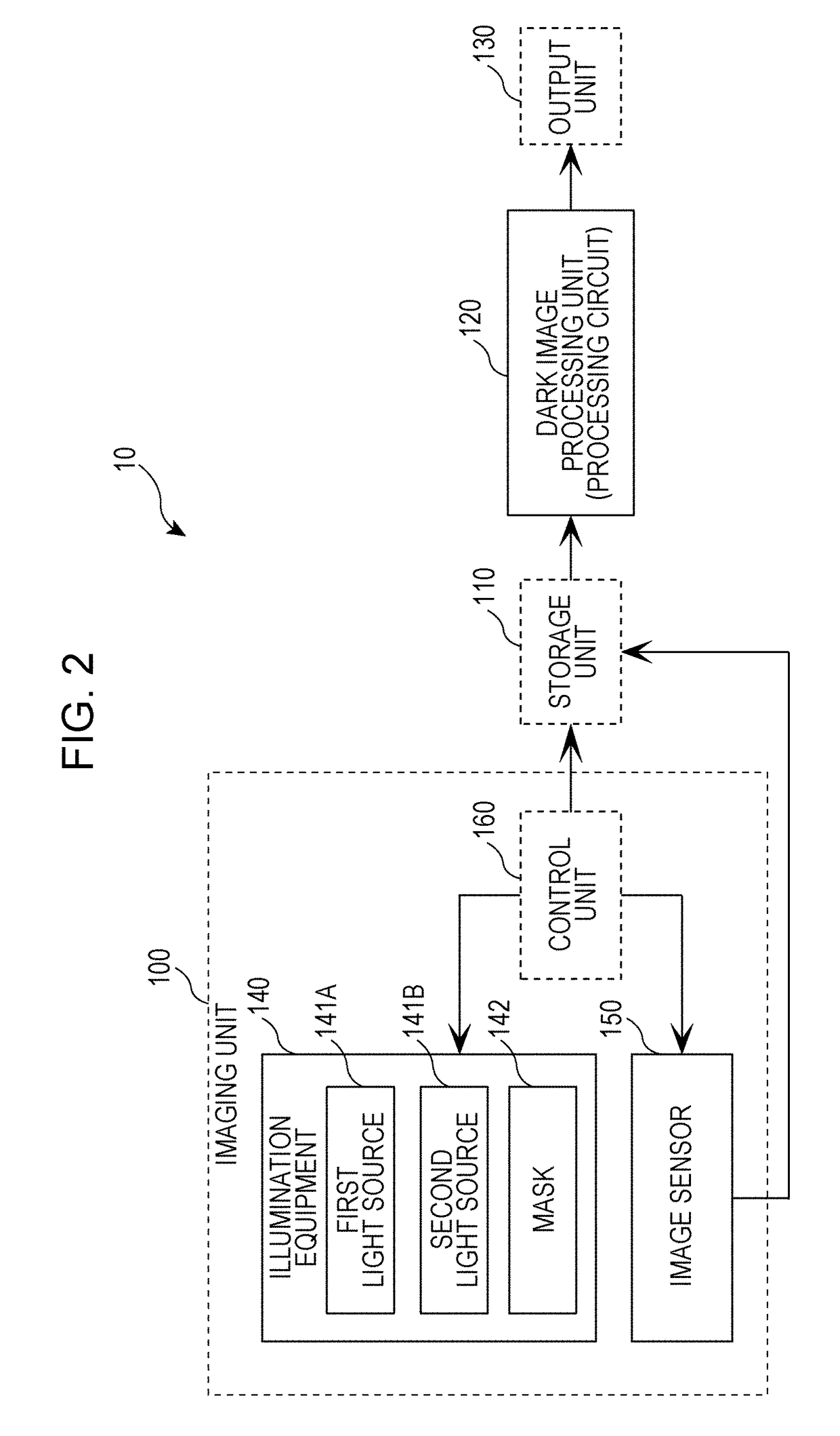
[0072]An image generating apparatus according to Embodiment 1 is provided with: illumination equipment made up of multiple point light sources and a mask in which are created a light-transmitting part that transmits light and a light-blocking part that blocks light, such as stripes or a checker pattern; an image sensor; and a processing circuit. In the illumination equipment, the multiple point light sources at different positions successively illuminate an object (that is, a material) positioned on top of the image sensor. At this time, the image sensor images the object while light and dark patterns of the light reaching the image sensor and the object are switched. As a result, multiple images with different light and dark patterns are acquired. For each pixel of the image sensor, the processing circuit extracts the pixel of lowest brightness (the dark of the light and dark patterns) from among multiple images, and generates an image.
[0073]At this point, the image generating appa...
embodiment 2
[0154]In Embodiment 1, each pixel is imaged over a sequence of images that includes one or more periods of a bright segment and a dark segment, and for each pixel position, the minimum brightness value is decided from among the multiple images, and the brightness value of the pixel at that pixel position in the dark image is decided. In Embodiment 2, the arrangement of objects (for example, cells included in an embryo) is specified by analyzing the brightness distribution of the dark image generated by the dark image process of Embodiment 1. Hereinafter, Embodiment 2 will be described in detail.
[0155]FIG. 18 is a function block diagram of the image generating apparatus 10 according to Embodiment 2.
[0156]The image generating apparatus 10 according to Embodiment 2 is provided with all of the structural elements of the image generating apparatus 10 of Embodiment 1, and additionally is provided with a cell position specification unit 210. Note that the cell position specification unit 2...
embodiment 3
Modification of Embodiment 3
[0221]In the present modification, the abnormal cell detection unit 220 stores a predetermined determination value as brightness determination criteria.
[0222]FIG. 32 is a function block diagram illustrating a detailed configuration of the abnormal cell detection unit 220 according to the modification of Embodiment 3. As illustrated in FIG. 32, the abnormal cell detection unit 220 according to the present modification is provided with all of the structural elements of the abnormal cell detection unit 220 of Embodiment 3 above, and in addition, is provided with a determination criteria storage unit 225.
[0223]The determination criteria storage unit 225 stores a predetermined brightness determination value (for example, 1300).
[0224]In the case in which the average brightness value of a cell region falls below the determination value, for example, the abnormality determination unit 224 judges that the cell corresponding to the cell region is abnormal.
[0225]FIG...
PUM
Abstract
An image generating apparatus is provided with a first light source and a second light source, an image sensor, a mask including a light-transmitting part and a light-blocking part, and a dark image processing unit. The image sensor acquires a first image of the material when illuminated by the first light source, and acquires a second image of the material when illuminated by the second light source. The image sensor includes a first pixel region and a second pixel region. The light-blocking part is positioned between the first pixel region and the first light source. The light-blocking part is positioned between the first pixel region and the first light source. The dark image processing unit uses first pixel information corresponding to a first pixel region in the first image and second pixel information corresponding to a second pixel region in the second image to generate a third image.
Description
BACKGROUND1. Technical Field[0001]The present disclosure relates to an image generating apparatus that generates images, such as a lensless microscope, for example, and to an image generating method.2. Description of the Related Art[0002]Demand to observe cultured cells continuously without staining exists in the cultivation of cells for medical use and in testing for drugefficacy, as well as in many fields that use cultured cells for medical or industrial applications. However, since many cells are nearly colorless and transparent, observation is difficult because of the low contrast when imaging with an optical microscope using transmitted light. One factor for the low contrast is the scattering or refraction of light due to the medium around the subject to be imaged and the subject itself.[0003]Japanese Patent No. 5403458 illustrates a method of removing a noise component of reflected light from the brightness of two light and dark states, namely a state of radiation from an opt...
Claims
Application Information
Patent Timeline
Application Date:The date an application was filed.
Publication Date:The date a patent or application was officially published.
First Publication Date:The earliest publication date of a patent with the same application number.
Issue Date:Publication date of the patent grant document.
PCT Entry Date:The Entry date of PCT National Phase.
Estimated Expiry Date:The statutory expiry date of a patent right according to the Patent Law, and it is the longest term of protection that the patent right can achieve without the termination of the patent right due to other reasons(Term extension factor has been taken into account ).
Invalid Date:Actual expiry date is based on effective date or publication date of legal transaction data of invalid patent.

