Automatic nitrogen fill for a fire sprinkler system

a technology of automatic nitrogen filling and fire sprinkler, which is applied in the direction of container discharge methods, instruments, separation processes, etc., can solve the problems of piping and other metal systems in contact with water, air or other chemicals, which are often subject to chemical corrosion, and the internal surface treatment of pipes is not easy to achieve. , to achieve the effect of improving the safety of operation

Active Publication Date: 2018-08-02
POTTER ELECTRIC SIGNAL
View PDF2 Cites 8 Cited by
  • Summary
  • Abstract
  • Description
  • Claims
  • Application Information

AI Technical Summary

Benefits of technology

[0018]Because of these and other problems in the art, there is described herein a gas supply system which includes nitrogen generation. The gas supply system is designed for use with fire sprinkler systems and includes a control system which uses the volumetric flow demand to automatically determine the mode of operation and switch between providing air and nitrogen. The gas supply system c

Problems solved by technology

Piping and other metal systems in contact with water, air, or other chemicals are often subject to chemical corrosion where the metals' contact with the substance can cause a reaction altering the chemical structure of the metal.
Oxygen gas corrosion is present generally wherever metallic composites are exposed to atmospheric or oxygen laden water conditions.
MIC is most commonly problematic in piping systems and occurs in a variety of industrial and other venues such as, but not limited to, fire protection sprinkler pipeline systems, water treatment facilities, cooling towers, oil and gas pipelines and production equipment, nuclear power plants, ocean and river shipping vessels, or in other places where microbes are generally introduced to the system via water contact.
In piping systems treatment of the internal surface of the pipe, which is often not readily accessible once the system is installed, can be difficult.
This can be particularly true in generally sealed piping systems such as wet pipe fire protection systems which are often filled with stagnant, relatively inaccessible water where access requires the significant expense of draining and refilling the system.
Dry and pre-action f

Method used


Image

  • Automatic nitrogen fill for a fire sprinkler system
  • Automatic nitrogen fill for a fire sprinkler system

Examples


Embodiment Construction

)

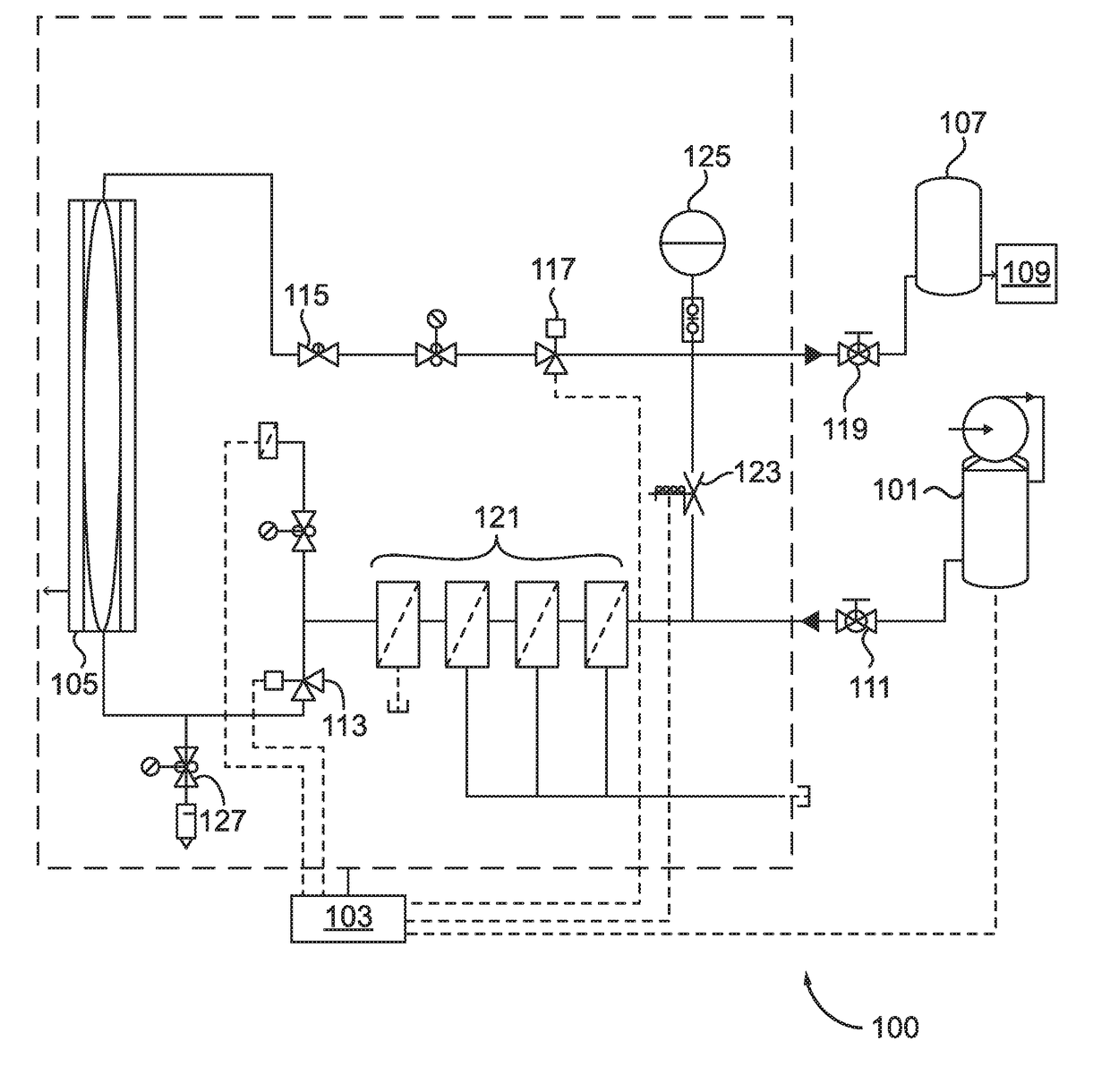
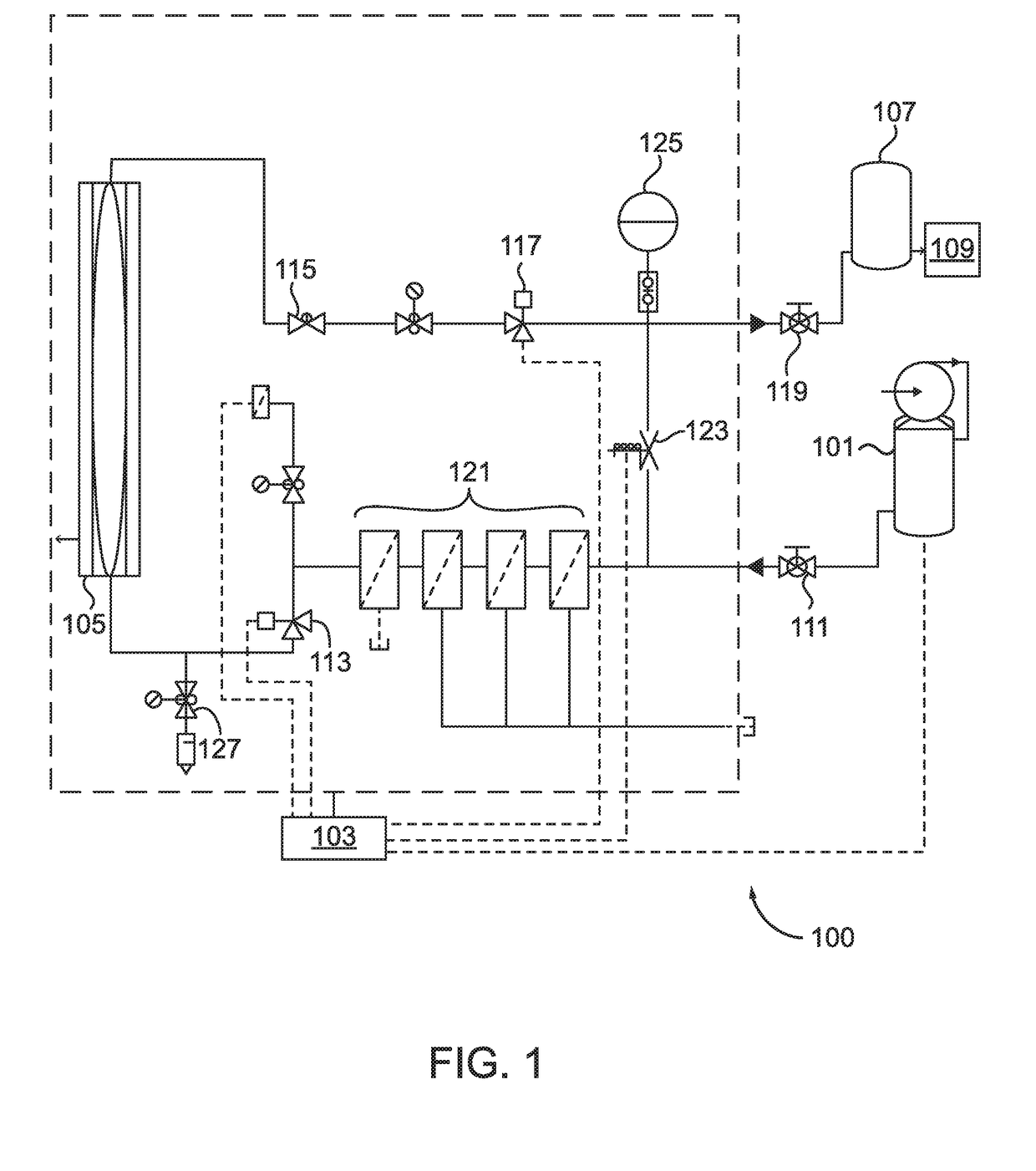
[0028]It will be readily understood that the components of the present invention, as generally described and illustrated in the FIGURES herein, could be arranged and designed in a wide variety of different configurations, thus, the following more detailed description of the embodiments of a system as represented in FIG. 1 is not intended to limit the scope of the invention, as claimed, but is merely representative of a presently preferred embodiment.

[0029]Throughout this disclosure, the term “computer” describes hardware which generally implements functionality provided by digital computing technology, particularly computing functionality associated with microprocessors. The term “computer” is not intended to be limited to any specific type of computing device, but it is intended to be inclusive of all computational devices including, but not limited to: processing devices, microprocessors, personal computers, desktop computers, laptop computers, workstations, terminals, servers, c...


PUM


Abstract

A gas supply system primarily designed for use with fire sprinkler systems which includes a control system which uses flow demand to automatically determine the mode of operation and switch between providing air and nitrogen. The gas supply system can operate either in standard nitrogen generation mode where nitrogen is supplied to the reservoir tank and/or sprinkler system or in a bypass mode, where sufficient pressure is only obtained by directly supplying air. The gas supply system can provide for improved safety in operation as well as the ability to operate the sprinkler system primarily when filled with nitrogen supervisory gas.

Description

CROSS REFERENCE TO RELATED APPLICATION(S)[0001]This application claims the benefit of U.S. Provisional Patent Application 62 / 452,113, filed Jan. 30, 2017, the entire disclosure of which is herein incorporated by reference.BACKGROUND1. Field of the Invention[0002]The present invention generally relates to corrosion inhibiting systems for fire sprinklers. Particularly to systems which can provide nitrogen or air to a dry pipe fire sprinkler system automatically depending on requirements of the sprinkler system.2. Description of the Related Art[0003]Piping and other metal systems in contact with water, air, or other chemicals are often subject to chemical corrosion where the metals' contact with the substance can cause a reaction altering the chemical structure of the metal. The most well known type of chemical corrosion of metal is rust, or the oxidation of iron. Oxygen gas corrosion is present generally wherever metallic composites are exposed to atmospheric or oxygen laden water con...

Claims


Application Information

Patent Timeline
IPC IPC(8): A62C35/68A62C35/62G05D7/06A62C35/60B01D53/22B01D53/30B01D69/08
CPCA62C35/68A62C35/62G05D7/0635A62C35/60B01D53/22B01D53/30B01D69/08B01D2053/224B01D63/02A62C35/645A62C37/50B01D2256/10F17C13/00
Inventor TIHEN, JOSHUADECKER, TIMOTHY
Owner POTTER ELECTRIC SIGNAL
Why Eureka
Try Eureka