Detector for an optical detection of at least one object

a technology of optical detection and detector, applied in the direction of distance measurement, sustainable manufacturing/processing, instruments, etc., can solve the problems of ssdsc, one optical sensor, production, etc., and achieve the effect of easy recognition

Inactive Publication Date: 2018-08-16
TRINAMIX GMBH
View PDF1 Cites 20 Cited by
  • Summary
  • Abstract
  • Description
  • Claims
  • Application Information

AI Technical Summary

Benefits of technology

[0118]Accordingly, the detector according to the present invention may comprise at least one modulation device which may be capable of generating at least one modulated light beam traveling from the object to the detector and, thus, modulates the illumination of the object and/or at least one sensor region of the detector, such as at least one sensor region of the at least one longitudinal optical sensor. Preferably, the modulation device may be employed for generating a periodic modulation, such as by employing a periodic beam interrupting device. By way of example, the detector can be designed to bring about a modulation of the illumination of the object and/or at least one sensor region of the detector, such as at least one sensor region of the at least one longitudinal optical sensor, with a frequency of 0.05 Hz to 1 MHz, such as 0.1 Hz to 10 kHz. Within this regard, the modulation of the illumination is understood to mean a process in which a total power of the illumination is varied, preferably periodically, in particular with a single modulation frequency or, simultaneously and/or consecutively, with a plurality of modulation frequencies. In particular, a periodic modulation can be effected between a maximum value and a minimum value of the total power of the illumination. Herein, the minimum value can be 0, but can also exceed 0, such that, by way of example, complete modulation does not have to be effected. In a particularly preferential manner, the at least one modulation may be or may comprise a periodic modulation, such as a sinusoidal modulation, a square modulation, or a triangular modulation of the affected light beam. Further, the modulation may be a linear combination of two or more sinusoidal functions, such as a squared sinusoidal function, or a sin(t2) function, where t denotes time. In order to demonstrate particular effects, advantages and feasibility of the present invention the square modulation is, in general, employed herein as an exemplary shape of the modulation which representation is, however, not intended to limit the scope of the present invention to this specific shape of the modulation. By virtue of this example, the skilled person may rather easily recogniz

Problems solved by technology

Especially, a production of optical sensors comprising one of an organic solar cell, a dye solar cell, a dye-sensitized solar cell (DSC), preferably a solid-state dye-sensitized

Method used


Image

  • Detector for an optical detection of at least one object
  • Detector for an optical detection of at least one object
  • Detector for an optical detection of at least one object

Examples


Embodiment Construction

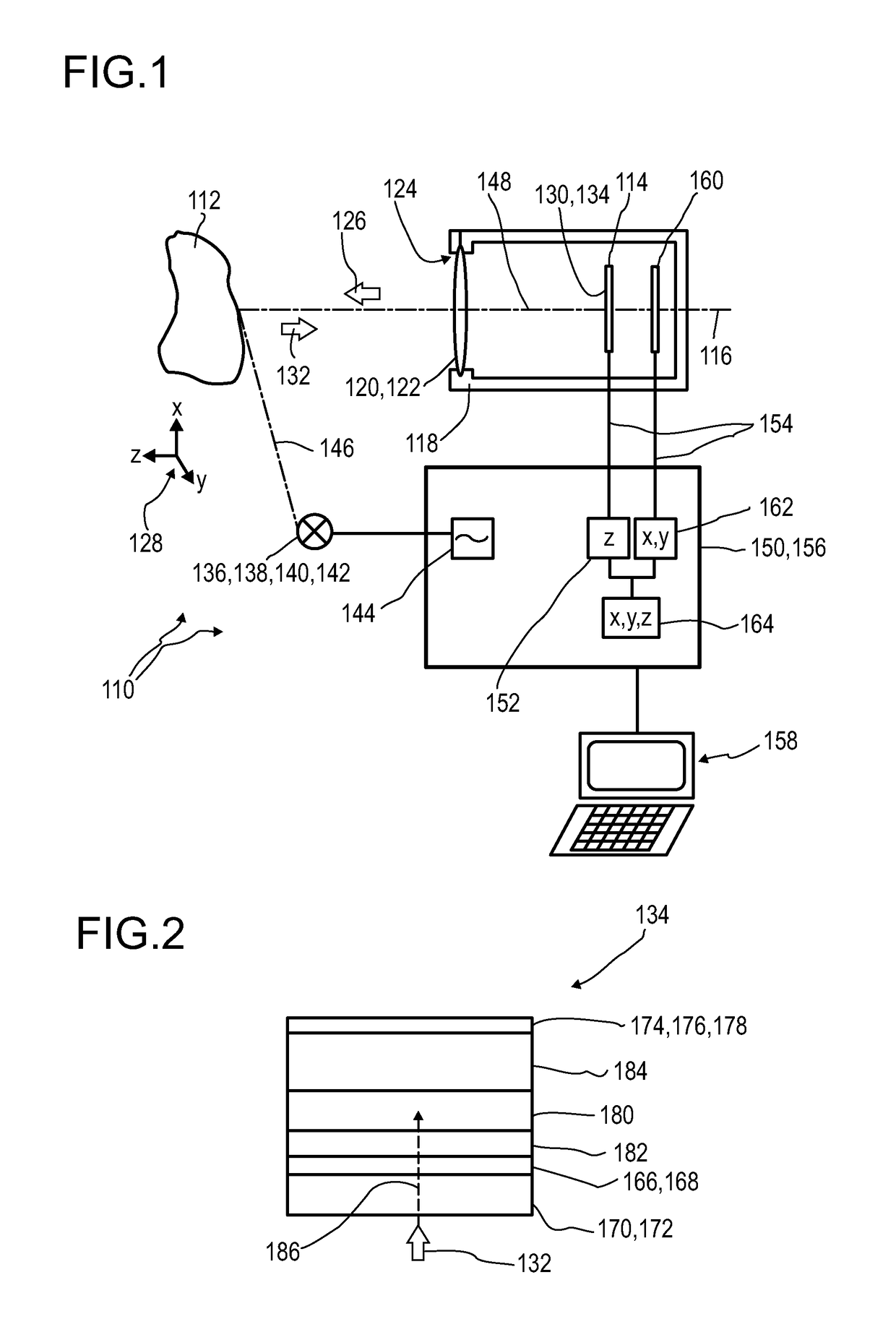
[0262]FIG. 1 illustrates, in a highly schematic illustration, an exemplary embodiment of an optical detector 110 according to the present invention, for determining a position of at least one object 112. However, other embodiments are feasible.

[0263]The optical detector 110 comprises at least one longitudinal optical sensor 114, which, in this particular embodiment, is arranged along an optical axis 116 of the detector 110. Specifically, the optical axis 116 may be an axis of symmetry and / or rotation of the setup of the optical sensors 114. The optical sensors 114 may be located inside a housing 118 of the detector 110. Further, at least one transfer device 120 may be comprised, preferably a refractive lens 122. An opening 124 in the housing 118, which may, particularly, be located concentrically with regard to the optical axis 116, preferably defines a direction of view 126 of the detector 110. A coordinate system 128 may be defined, in which a direction parallel or antiparallel to...


PUM

PropertyMeasurementUnit
Poweraaaaaaaaaa
Electric chargeaaaaaaaaaa
Areaaaaaaaaaaa

Abstract

Disclosed herein is a detector (110) for an optical detection of at least one object (112) the detector (110) including: (a) at least one longitudinal optical sensor (114) having at least one sensor region (130), the longitudinal optical sensor (114) containing at least one photodiode (134) the photodiode (134) having at least two electrodes (166, 174), wherein at least one photoactive layer (180) containing at least one electron donor material and at least one electron acceptor material is embedded between the electrodes (166, 174); and (b) at least one evaluation device (150) designed to generate at least one item of information on a longitudinal position of the object (112) by evaluating the longitudinal sensor signal. The detector (110) is efficient for accurately determining of a position of at least one object (112) in space, and exhibits an FiP effect with an improved signal-to-noise ratio.

Description

FIELD OF THE INVENTION[0001]The invention relates to a detector for an optical detection of at least one object, in particular, for determining a position of at least one object, specifically with regard to a depth or both to the depth and a width of the at least one object. Furthermore, the invention relates to a human-machine interface, an entertainment device, a scanning device, a tracking system and a camera. Further, the invention relates to a method for optical detection of at least one object and to various uses of the detector. Such devices, methods and uses can be employed for example in various areas of daily life, gaming, traffic technology, mapping of spaces, production technology, security technology, medical technology or in the sciences. However, further applications are possible.PRIOR ART[0002]Various detectors for optically detecting at least one object are known on the basis of optical detectors. WO 2012 / 110924 A1 discloses an optical detector comprising at least o...

Claims


Application Information

Patent Timeline
IPC IPC(8): G01C3/08G01S3/781G01S3/786G01S17/46G01S7/481H01L27/30H01L51/42H01L51/44
CPCH01L51/0037H01L51/0035H01L51/0043H01L51/004H01L51/0036H01L51/4273H01L51/442G01S3/781G01S3/786G01S17/46G01S7/4816H01L27/307H01L51/0047G01C3/08Y02E10/549Y02P70/50H10K39/32H10K30/30H10K30/82H10K30/353H10K85/111H10K85/113H10K85/141H10K85/151H10K85/215H10K85/1135
Inventor SEND, ROBERTBURDER, INGMARLUNGENSCHMIED, CHRISTOPH
Owner TRINAMIX GMBH
Why Eureka
Try Eureka