
Method of repairing turbine component using ultra-thin plate

a technology of ultra-thin plates and turbine components, which is applied in the direction of machines/engines, non-electric welding apparatuses, crystal growth processes, etc., can solve the problems of difficult welding of superalloy materials

Active Publication Date: 2018-08-23
GENERAL ELECTRIC CO
View PDF12 Cites 21 Cited by
  • Summary
  • Abstract
  • Description
  • Claims
  • Application Information

AI Technical Summary

Benefits of technology

The present invention relates to a method of manufacturing a metal object by placing a plate on top of a cast component and creating an overhang, depositing metallic powder onto the plate and irradiating it to form a fused layer, until the metal object is formed. The method can be used for repairing or joining the plate to the cast component. The technical effects include improved manufacturing efficiency, reduced labor costs, and improved quality of metal objects. The invention also provides a method for manufacturing a turbine blade or vane by placing a plate on top of a cast component, depositing metallic powder onto the plate, and irradiating it until the metal object is formed, with the overhang being removed.

Problems solved by technology

Superalloy materials are among the most difficult materials to weld due to their susceptibility to weld solidification cracking and strain age cracking.
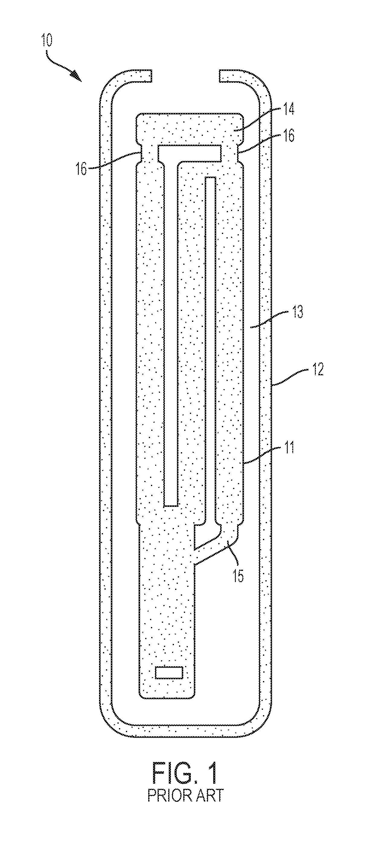
In view of the foregoing, and the fact that current blades and vanes tend to be life limited especially at their tips which are very expensive to replace, a need remains for novel methods of manufacturing tips or other components for new-make cast airfoils and field-return repair airfoils.

Method used


Image

  • Method of repairing turbine component using ultra-thin plate
  • Method of repairing turbine component using ultra-thin plate
  • Method of repairing turbine component using ultra-thin plate

Examples


Embodiment Construction

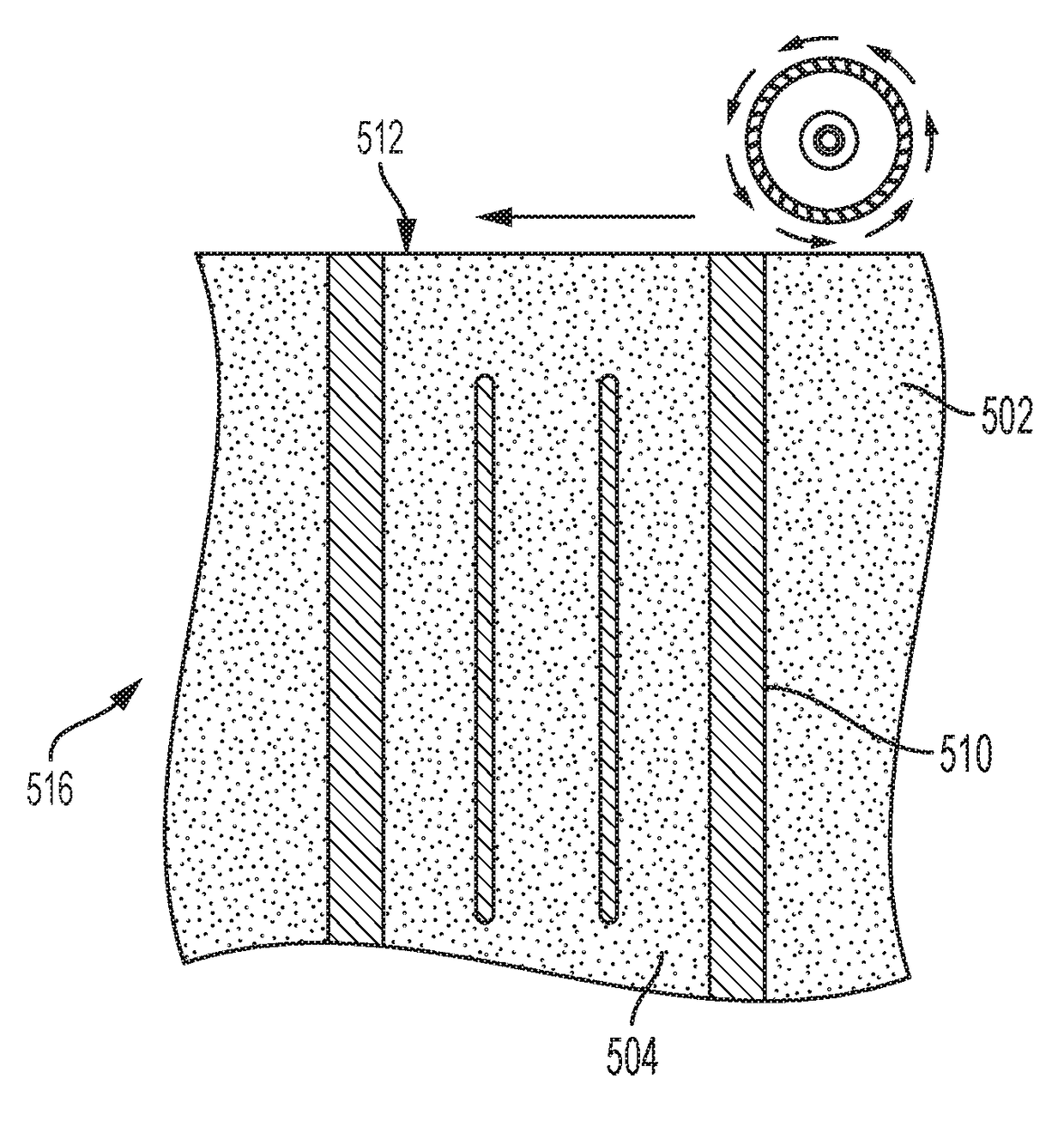
[0037]The detailed description set forth below in connection with the appended drawings is intended as a description of various configurations and is not intended to represent the only configurations in which the concepts described herein may be practiced. The detailed description includes specific details for the purpose of providing a thorough understanding of various concepts. However, it will be apparent to those skilled in the art that these concepts may be practiced without these specific details. For example, the present invention provides a preferred method for additively manufacturing certain components of metal objects, and preferably these components and these objects are used in the manufacture of jet aircraft engines. Specifically, the production of single crystal, nickel-based superalloy or elemental titanium hollow metal objects such as turbine blades and stator vanes can be advantageously produced in accordance with this invention. However, other metal components of ...


PUM

PropertyMeasurementUnit
thicknessaaaaaaaaaa
heightaaaaaaaaaa
heightaaaaaaaaaa

Abstract

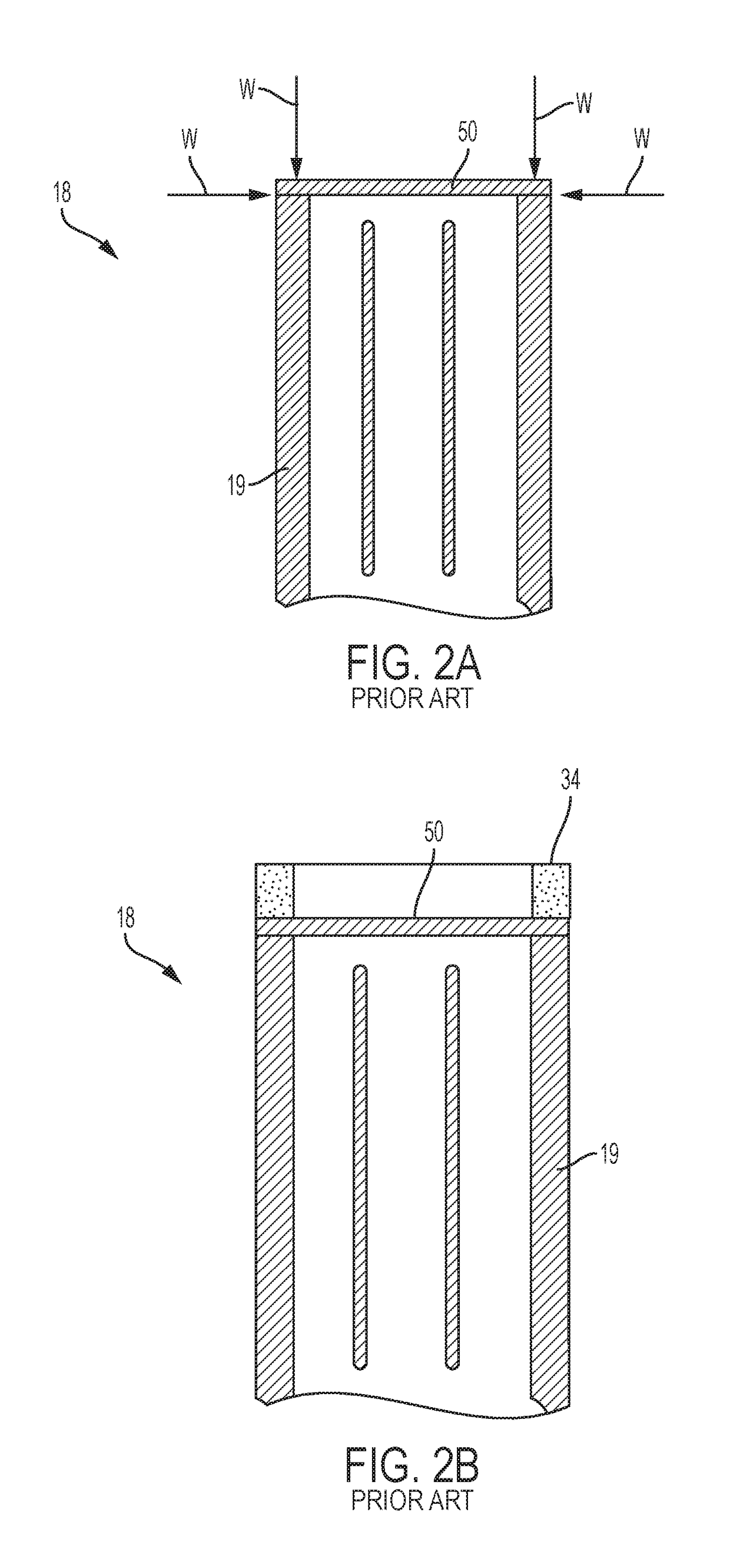
Methods of manufacturing or repairing a turbine blade or vane are described. The airfoil portions of these turbine components are typically manufactured by casting in a ceramic mold, and a surface made up of the cast airfoil and at the least the ceramic core serves as a build surface for a subsequent process of additively manufacturing the tip portions. The build surface is created by removing a top portion of the airfoil and the core, or by placing an ultra-thin shim on top of the airfoil and the core. The overhang projected by the shim is subsequently removed. These methods are not limited to turbine engine applications, but can be applied to any metallic object that can benefit from casting and additive manufacturing processes. The present disclosure also relates to finished and intermediate products prepared by these methods.

Description

INTRODUCTION[0001]The present disclosure generally relates to a method of manufacturing or repairing a hollow metal object. More specifically, the hollow metal object is prepared using an additive manufacturing (AM) technique, or a mixture of an AM technique and of an investment casting technique. The AM technique utilized in the manufacturing method is not limited to the direct metal laser melting (DMLM) or any other laser powder-bed fusion additive manufacturing. The hollow metal object produced is especially useful as a component of an aircraft engine or other power generation turbines, e.g. a blade or a stator vane.BACKGROUND[0002]Superalloy materials are among the most difficult materials to weld due to their susceptibility to weld solidification cracking and strain age cracking. The term “superalloy” as used herein means a highly corrosion and oxidation resistant alloy with excellent mechanical strength and resistance to creep at high temperatures. Superalloys typically includ...

Claims


Application Information

Patent Timeline
Patent Type & Authority Applications(United States)
IPC IPC(8): B23P6/04F01D5/00B22F5/04B23P6/00B23K20/22B23K35/02F01D5/14B23K26/34
CPCB23P6/045B23K2103/26B22F5/04B23P6/007B23K20/22B23K35/0244B23K2203/26B23K26/34B22F3/105B23K26/0624B23K2201/001B23K2203/08F01D5/147B23K2101/001B23K2103/08F01D5/005F05D2230/30F01D5/187F01D9/065F05D2230/22F05D2240/307F05D2230/31F05D2240/125B22F7/062B22F7/08B22F2003/245C30B29/52B22F2998/10B22F2999/00B22F5/009C30B29/66C30B13/24Y02P10/25B33Y10/00B23P6/002B22F10/28B22F12/17B22F10/66B22F10/38B22F10/32B22D15/00
Inventor GARAY, GREGORY TERRENCEMEYER, MARK KEVINKONITZER, DOUGLAS GERARDCARTER, WILLIAM THOMAS
Owner GENERAL ELECTRIC CO
Learn More