
Direct drive type dual turbo blower cooling structure

a dual-turbo blower and cooling structure technology, which is applied in the direction of machines/engines, liquid fuel engines, magnetic circuit shapes/forms/construction, etc., can solve the problems of reducing the durability of the entire driving unit, reducing the lifespan of the internal components, and largely transmitting the noise generated in the internal driving unit, so as to improve the cooling efficiency and increase the flow rate. , the effect of increasing the flow ra

Active Publication Date: 2018-08-23
TURBOWIN
View PDF31 Cites 4 Cited by
  • Summary
  • Abstract
  • Description
  • Claims
  • Application Information

AI Technical Summary

Benefits of technology

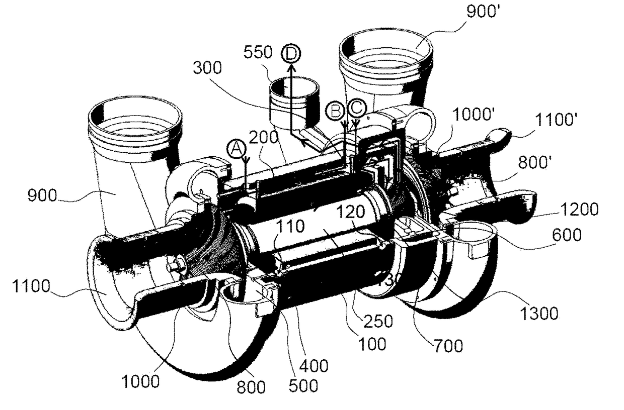
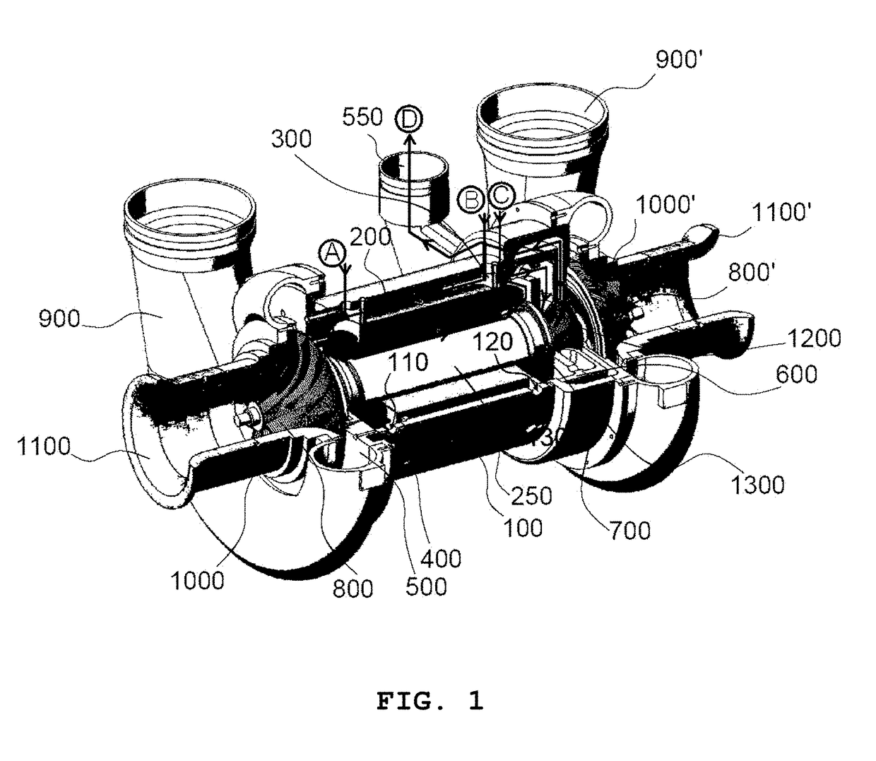
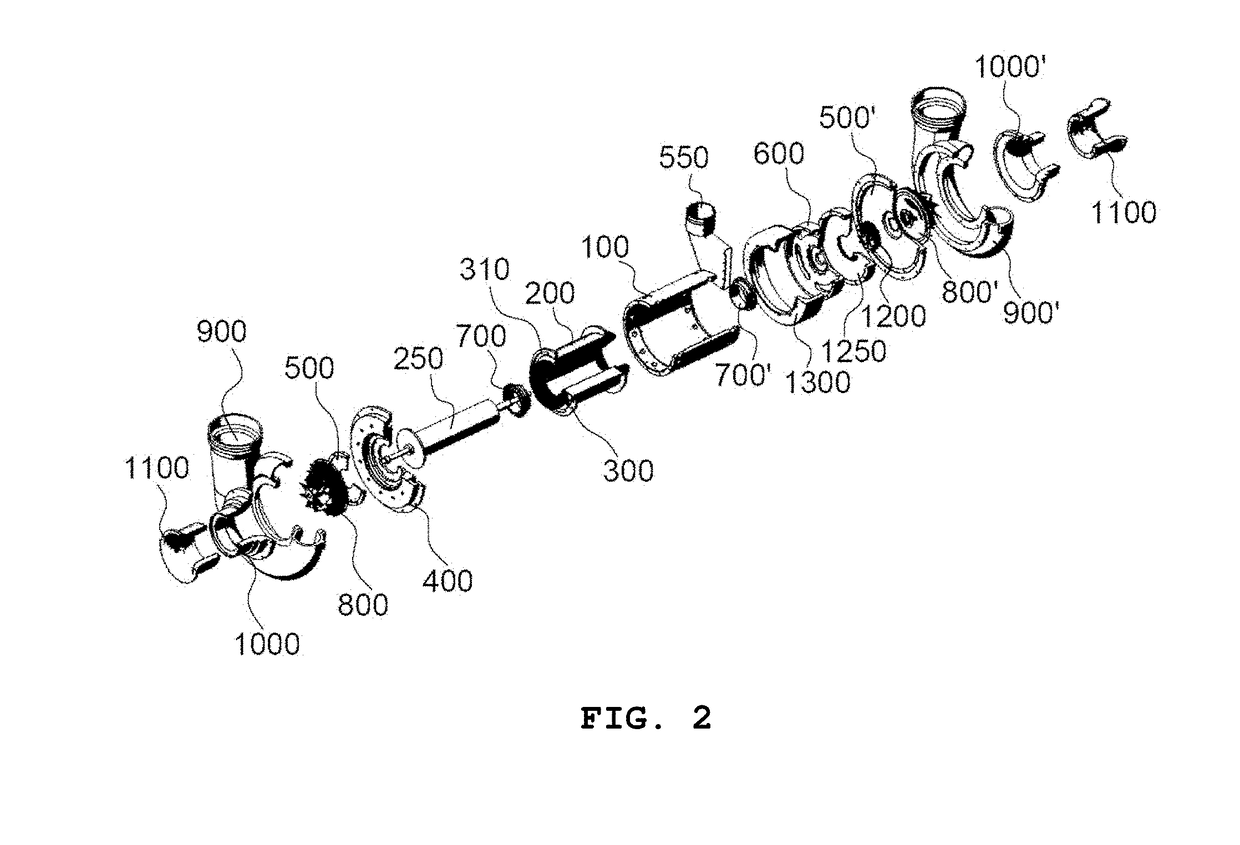
The direct drive type dual turbo blower cooling structure described in this patent increases the flow rate and provides better cooling efficiency by including multiple holes for cooling components in a motor. This prevents thermal unbalance and ensures cooling of all components. Additionally, this structure eliminates the need for additional components such as pumps, heat exchangers, water tanks, and pipes, reducing manufacturing time and cost.

Problems solved by technology

However, in the related art, the noise generated in the internal driving unit is largely transmitted to the outside.
Also, since the internal structure for properly cooling the internal components of the driving unit is not provided, there are defects in that the lifespan of the internal components is reduced and the durability of the entire driving unit is reduced.
In the former method, the power required for cooling is small, but it has a disadvantage that the sensitivity to the impeller is very high because the cooling system itself is closely interlocked with the impeller.
That is, since the structure of the cooling system is changed according to the design shape of the impeller, the degree of freedom of design is greatly restricted.
In addition, there is a problem in that the entire size of the turbo device is increased due to the characteristics of the cooling system.
The latter method has a disadvantage in that the cooling efficiency is very low because it has a structure of blowing a large amount of air therein by a considerable pressure by using a cooling fan.
Accordingly, a cooling system that relies on a cooling fan has a problem of consuming a relatively large amount of power in order to maintain an appropriate level of cooling.
Since the introduced air cools the entire interior thereof, it is not enough to provide a regular cooling for each component.
As a result, the cooling efficiency thereof is reduced.
On the other hand, a both-end type turbo blower has been developed in the related art, but since impellers are disposed at both sides, there is a spatial limit in installation of a fan, and accordingly, a water cooling type and an impeller intake air type have been used.
In the water cooling type, since the subsidiary materials for cooling such as a pump, a heat exchanger, a water tank, a pipe, etc. are considerably necessary, the cost is increased.
Also, in order to affix them thereto, since the separate space is necessary in the package, there is a disadvantage in that the equipment becomes bigger.
In addition, if a leak occurs, it may lead to big accidents owing to the equipment that uses high voltage.
However, there is a drawback in that it is not possible to affix the nozzle thereto.
That is, in the conventional both-end type turbo blower, turbo blower, since it is difficult to configure and install the fan, it has no choice but to use the water cooing method and the air cooling method using the impeller intake air, though the manufacturing cost is increased and the efficiency is lowered.

Method used


Image

  • Direct drive type dual turbo blower cooling structure
  • Direct drive type dual turbo blower cooling structure
  • Direct drive type dual turbo blower cooling structure

Examples


Embodiment Construction

[0072]Since the description of the present invention is a mere embodiment for structural and functional description, it must not be interpreted that the scope of the present invention is limited by the embodiments described in the text. That is, since the embodiments can be variously changed and have various forms, it should be understood that the scope of the invention includes the equivalents for realizing the technical concept. Also, since the specific embodiments do not include all objects and effects presented by the present invention, the scope of the present invention is not limited by them.

[0073]Therefore, the implementation examples of this invention are nothing more than simple examples in all respects and will not be interpreted restrictively.

[0074]Even though the terms such as 1, 2, and others can be used to explain many components, the above components shall not be limited by the above terms.

[0075]The terms used in this application do not intend to limit this invention,...


PUM


Abstract

The present invention relates to a direct drive type dual turbo blower cooling structure and, more particularly, to a direct drive type dual turbo blower cooling structure in which a plurality of hole portions for cooling a stator and a plurality of hole portions for cooling a coil portion, a bearing housing, and a rotor are formed along the inner diameter of a motor casing; impellers are disposed on both sides thereof, such that a flow rate is doubled; and an air cooling system capable of achieving thermal balance through the plurality of hole portions is implemented at the time of operation of a cooling fan which provides an air cooling system instead of a conventional water cooling system. As such, it is possible to simplify the mechanical structure and reduce manufacturing time and costs because the pump, heat exchanger, water tank, pipes, etc. required for a water cooling system are unnecessary.

Description

TECHNICAL FIELD[0001]The present invention relates to a direct drive type dual turbo blower cooling structure and, more particularly, to a direct drive type dual turbo blower cooling structure which includes a plurality of holes for cooling a stator along an outer diameter of a motor casing, a plurality of holes for cooling a coil part, a bearing housing, and a rotor, and impellers at both sides to increase flow rate and realize an air cooling type which can achieve thermal balance through a plurality of holes when a cooling fan not for water cooling type of the related art, but for an air cooling type is operated, and thus has a simple mechanical structure without a pump, a heat exchanger, a water tank, and pipes etc. required for a water cooling type, thereby reducing manufacturing time and cost.BACKGROUND ART[0002]Generally, a blower is a mechanical device that generates energy of a fluid. The blower includes of an impeller that generates a flow, and a casing that guides a flow c...

Claims


Application Information

Patent Timeline
Patent Type & Authority Applications(United States)
IPC IPC(8): F04D29/58F04D19/04H02K5/20H02K9/06
CPCF04D29/5806F04D19/042H02K5/20H02K9/06F04D25/0653H02K1/20H02K9/04H02K5/207F04D17/105F04D25/0606F04D25/082F04D25/166
Inventor KIM, MINSOOPARK, YOUNGKYU
Owner TURBOWIN
Learn More