
Method for detecting electrical faults in a current supply of a consumer

a current supply and consumer technology, applied in the direction of power supply testing, instruments, measurement devices, etc., can solve the problems of not allowing a conclusion as to the precise fault source, difficult to detect damage in the vehicle wiring that is not always manifesting fully, etc., to achieve clear separation, increase transition resistance, and increase the effect of transition resistan

Active Publication Date: 2018-08-23
ROBERT BOSCH GMBH
View PDF3 Cites 0 Cited by
  • Summary
  • Abstract
  • Description
  • Claims
  • Application Information

AI Technical Summary

Benefits of technology

The present invention provides a method of detecting damaged power wiring in vehicles. This is difficult to do through simple monitoring of supply voltage, but the present invention can detect developing faults at an early stage. It can detect changes in resistance in plug connectors, fuses, cables, and circuit board or welded connections, which could lead to wide-ranging service-facility stays. The method is preferably a software function that can be used on a wide variety of control units and is advantageously distributed application software in a computer network. It is low-cost and can be easily realized, and can be downloaded via computer networks.

Problems solved by technology

If the transition resistance significantly differs from an expected value, then this points to an electrical fault in the current supply.
However, this method of approach places the focus only on the individual control unit with its actuators.
Damage in the vehicle wiring that is not always manifesting fully is extremely difficult to detect through simple monitoring of the supply voltage.
Generally, conventional voltage measurements are merely able to detect overvoltage and undervoltage faults, which, however, do not allow a conclusion as to the precise fault source.
Conventionally, such faults may lead to wide-ranging service-facility stays because they can be detected and allocated only with the greatest of difficulties.

Method used


Image

  • Method for detecting electrical faults in a current supply of a consumer
  • Method for detecting electrical faults in a current supply of a consumer
  • Method for detecting electrical faults in a current supply of a consumer

Examples


Embodiment Construction

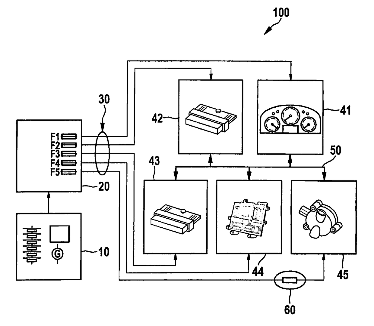
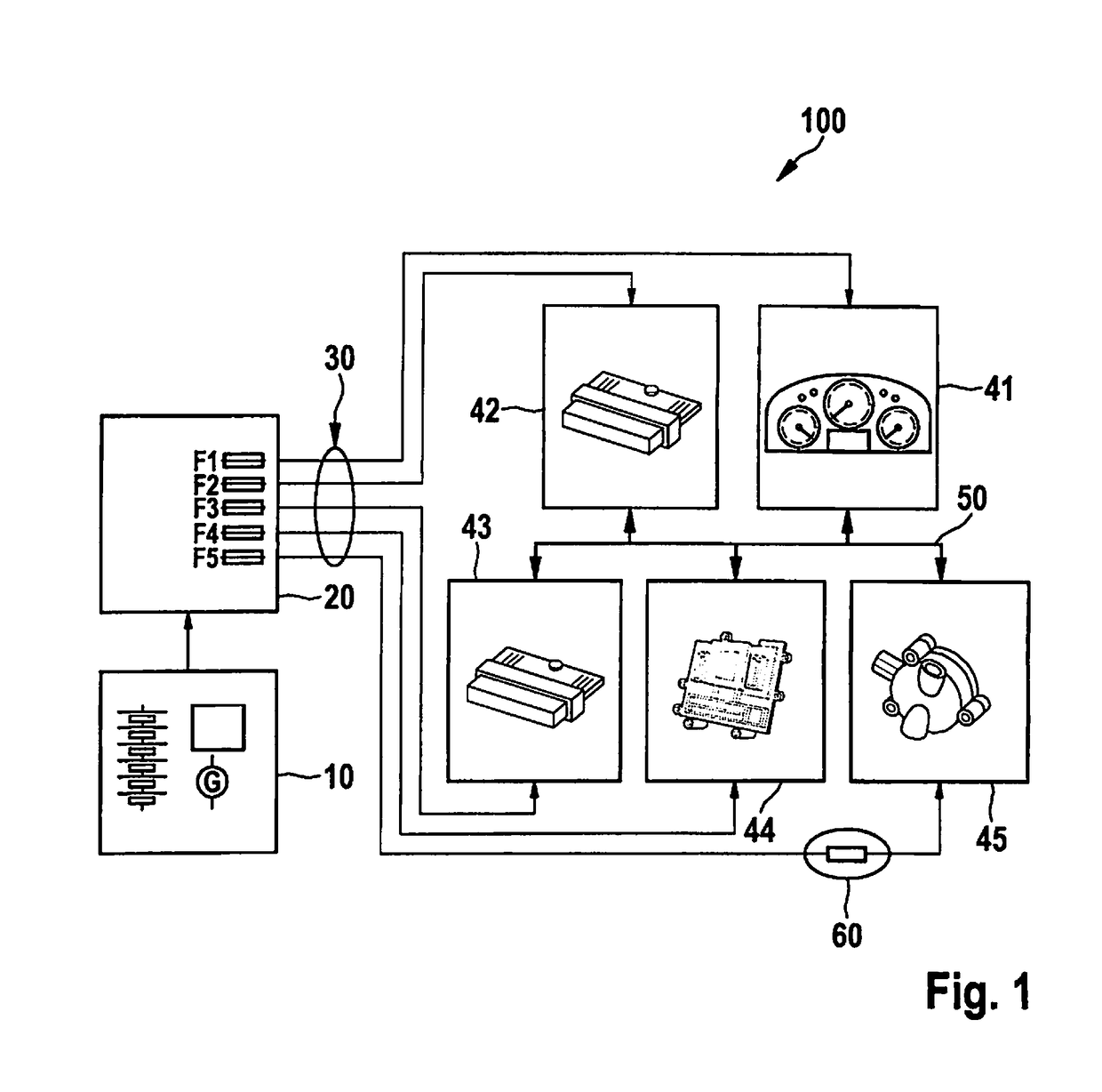
[0016]FIG. 1 shows a vehicle electrical system 100 as it may form the basis of the present invention, in the form of a wiring diagram. Vehicle electrical system 100 has an electrical current supply 10, which includes a generator and a battery, in particular. Current supply 10 is connected to a fuse box 20 having individual fuses F1, F2, . . . , which are meant to protect connected consumers from an overcurrent.

[0017]Different consumers such as control units 41-45 are connected via a cable harness 30. The control units may in particular involve what is known as an instrument cluster 41 for driver information, a vehicle control unit 42 (VCU) for specifying the driving and operating strategies, a gearbox control unit 43 (GCU) for the gear selection, an engine control unit 44 (ECU) for controlling the internal combustion engine, and a pump control unit 45 (PCU) for controlling a fuel pump. The control units are connected in a data-transmitting manner by way of a data bus 50, such as a C...


PUM


Abstract

A method for detecting an electrical fault in a current supply of a consumer, where a transition resistance of the current supply allocated to the consumer is determined from a local voltage value allocated to the consumer, a local current value allocated to the consumer, and a global voltage value, and compared to a resistance threshold value allocated to the consumer, and an electrical fault in the current supply of the consumer is detected as a function of the comparison result.

Description

CROSS REFERENCE[0001]The present application claims the benefit under 35 U.S.C. § 119 of German Patent Application No. DE 102017202594.8 filed on Feb. 17, 2017, which is expressly incorporated herein by reference in its entirety.FIELD[0002]The present invention relates to a method for detecting an electrical fault in a current supply of a consumer; it also relates to a computer unit and a computer program for its execution.BACKGROUND INFORMATION[0003]German Patent No. DE 10 2014 018 643 B3 describes the generation of a voltage-reference value from a plurality of measured values of control units in a central master device. The control units are equipped with voltage-measuring devices and make the measured voltage values available to the central master device; the central master device then supplies the reference value to each control unit, so that they are able to ascertain a correction value for calibrating the voltage-measuring device.[0004]German Patent No. DE 10 2004 023 084 B3 d...

Claims


Application Information

Patent Timeline
Patent Type & Authority Applications(United States)
IPC IPC(8): G01R31/28G01R31/327G01R19/165G06F1/30
CPCG01R31/2879G01R31/3275G01R19/16566G06F1/30G01R31/40G06F1/28
Inventor JENNE, ACHIMFOERCH, ULRICH
Owner ROBERT BOSCH GMBH
Learn More