
Gradient Field Optically Pumped Magnetometer

a magnetometer and gradient field technology, applied in the field of magnetic gradient field sensing, can solve the problems of difficult to maintain a supply of cryogenics, complex cooling technology, bulky and expensive,

Inactive Publication Date: 2018-08-23
QUSPIN
View PDF4 Cites 42 Cited by
  • Summary
  • Abstract
  • Description
  • Claims
  • Application Information

AI Technical Summary

Benefits of technology

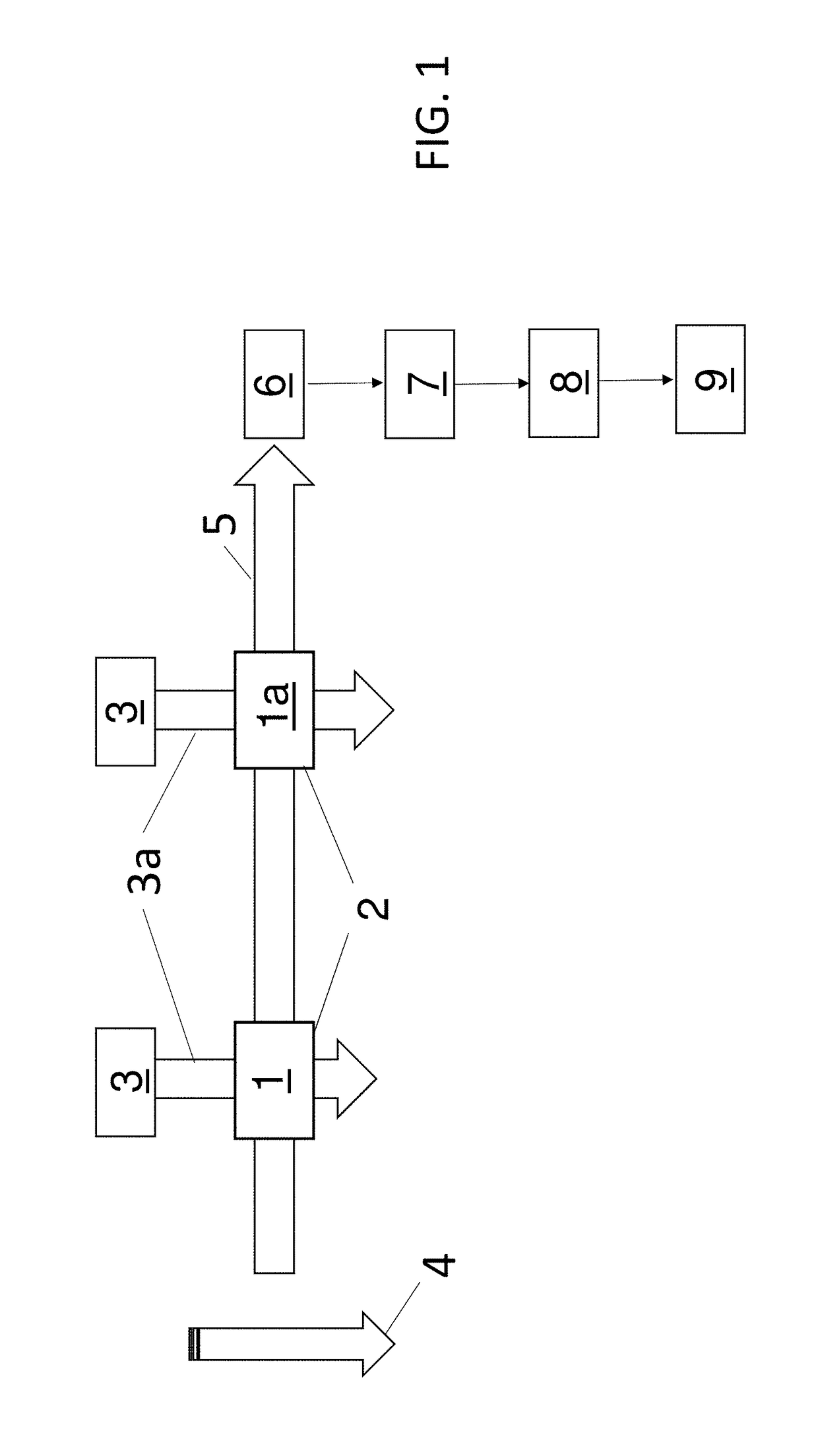
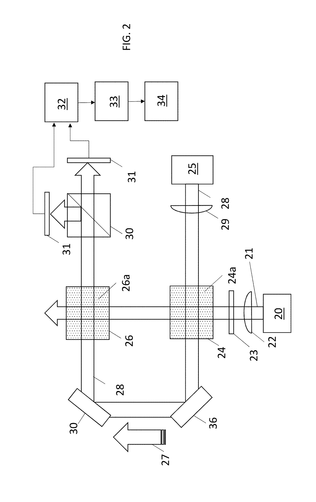
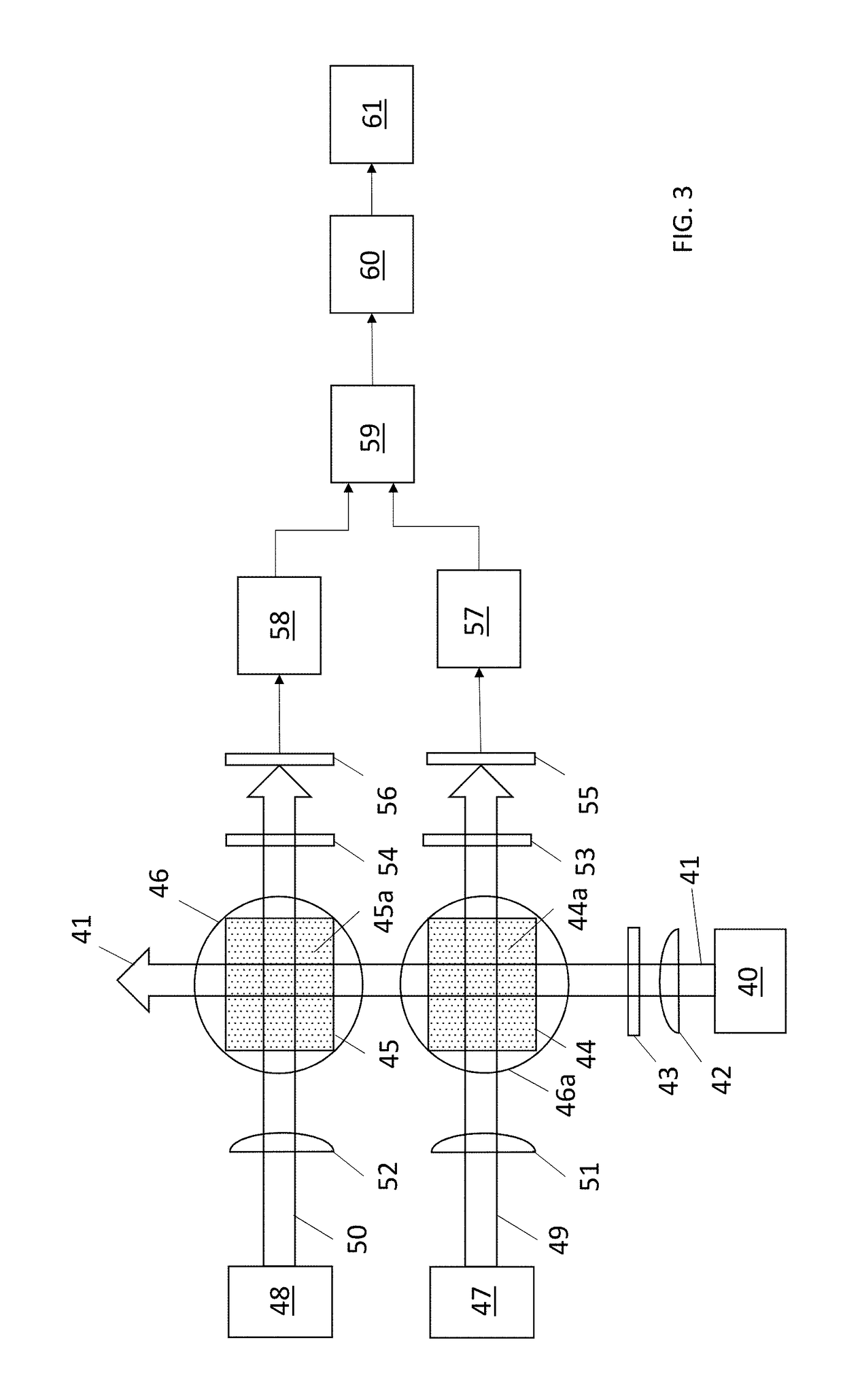
The patent describes a new gradiometer that can measure magnetic fields with very high sensitivities and can operate in high ambient magnetic fields. The device uses a special technique called optical pumping to monitor the precession of atomic spins. The gradiometer can be used in proton magnetometers and low-field NMR applications. It has a high sensitivity to magnetic fields and can measure the magnetic field gradient without being affected by external factors. The gradiometer uses two vapor cells or sets of atoms separated by a distance called the baseline, which helps to create a stable magnetic field measurement. Overall, the gradiometer is a useful tool for measuring magnetic fields with high accuracy.

Problems solved by technology

SQUIDs must be cooled to cryogenic temperatures, and the technologies involved in cooling are complex, bulky, and expensive.
This has proven to be a major roadblock in the mass market commercialization of SQUID technologies for many promising remote sensing applications in both the civilian and defense sector.
Because OPMs do not need cryogenic cooling to operate, the cost and complexity associated with OPMs is significantly lower and enables the operation in remote environments, where maintaining a supply of cryogenics is difficult.
Zero-field OPM sensors with high sensitivities have been implemented into compact sensors, but major limitations restrict their use including: (1) To reach very high sensitivity, OPMs must operate in a very low ambient magnetic field environment, and (2) OPMs are pure magnetometers making them highly susceptible to ubiquitous magnetic noise.
While this scheme has proven good performance, it requires precise tuning of the parameters in both vapor cells, which can be a tedious task.

Method used


Image

  • Gradient Field Optically Pumped Magnetometer
  • Gradient Field Optically Pumped Magnetometer
  • Gradient Field Optically Pumped Magnetometer

Examples


example 1

[0025]As an example, a simple OPM gradiometer prototype was built as shown in FIG. 4. The gradiometer consists of two alkali vapor cells 76 and 77 separated by a distance, d, referred to as the baseline of the gradiometer. Light from a diode laser 70 at 795 nm was used to optically pump the electron spins of rubidium atoms 76a, 77a and simultaneously probe their free spin precession. The light beam 71 from the laser 70 was coupled into a polarization-maintaining optical fiber 73 with a lens 72 and delivered to the physics package 88. A physics package 88, as used herein, comprised the physical components as opposed to the electrical / electronic components of the system. In this case, the items within the physics package 88 were built and then housed in a single confined unit. The light was expanded and collimated with a lens 74 to a 2 mm diameter beam. A quarter-wave plate 75, with its optical axis aligned to 22.5° with respect to the input polarization of the light produced, ellipti...


PUM


Abstract

A system and method to measure a magnetic gradient field with an optically-pumped magnetometer is described. Atoms are spin polarized at two locations. Larmor frequencies are, induced and the spin frequency is detected. The frequencies are proportional to the total magnetic field at the locations of the atoms. The magnetic field gradient is extracted from the beat frequency of the two Larmor frequencies.

Description

[0001]The following application is an application for patent under 35 USC 111 (a). This application claims priority to U.S. Provisional Application No. 62 / 460,292 filed Feb. 17, 2017 of common title and inventorship. This invention was made with government support of Defense Advanced Research Projects Agency Contract #D16PC00195. The government has certain rights in the invention.FIELD OF INVENTION[0002]This disclosure relates to the field of magnetic gradient field sensing, specifically a system and method thereof.BACKGROUND[0003]DC magnetic field measurements with femtotesla level resolution require highly sensitive magnetometers, such as Superconducting Quantum Interference Device (SQUID) magnetometers. SQUIDs must be cooled to cryogenic temperatures, and the technologies involved in cooling are complex, bulky, and expensive. This has proven to be a major roadblock in the mass market commercialization of SQUID technologies for many promising remote sensing applications in both th...

Claims


Application Information

Patent Timeline
IPC IPC(8): G01R33/26G01R33/32
CPCG01R33/323G01R33/26
Inventor SHAH, VISHALKNAPPE, SVENJAHUGHES, KENNETH JERAMIAHALEM, ORANGOSBORNE, JAMESORTON, JEFFREY
Owner QUSPIN
Learn More