
Magnetic tape

a magnetic tape and tape body technology, applied in the field of magnetic tapes, can solve the problems of significant damage to the edge portion of the magnetic tape, edge damage, and edge damage, and achieve the effect of preventing the occurrence of edge damag

Active Publication Date: 2018-08-23
FUJIFILM CORP
View PDF2 Cites 106 Cited by
  • Summary
  • Abstract
  • Description
  • Claims
  • Application Information

AI Technical Summary

Benefits of technology

The patent aims to provide a magnetic tape with a thin back coating layer that prevents edge damage. The technical effect is to improve the quality of the magnetic tape and to prevent any damage during the manufacturing process.

Problems solved by technology

However, in a case where the inventors have studied regarding the thinning of the back coating layer, it was clear that, particularly, in a magnetic tape in which a back coating layer is thinned to have a thickness equal to or smaller than 0.30 μm, a phenomenon in which an edge portion of the magnetic tape is damaged (hereinafter, referred to as “edge damage”) significantly occurs, after causing the magnetic tape to run in a drive.
In a case where disordered winding occurs at the time of this winding, an edge of the magnetic tape hits against a flange or the like of a reel and the edge damage may occur.
This edge damage may cause an increase in the number of errors at the time of recording and / or a deterioration of running stability.

Method used


Image

  • Magnetic tape
  • Magnetic tape
  • Magnetic tape

Examples


example 1

[0137]A list of components of each layer forming composition is shown below.

[0138]Magnetic Layer Forming Composition

[0139]Magnetic Solution

[0140]Ferromagnetic hexagonal barium ferrite powder: 100.0 parts[0141](coercivity Hc: 196 kA / m (2,460 Oe), average particle size (average plate diameter): 24 nm)

[0142]Oleic acid: 2.0 parts

[0143]A vinyl chloride copolymer (MR-104 manufactured by Zeon Corporation): 10.0 parts

[0144]SO3Na group-containing polyurethane resin: 4.0 parts[0145](Weight-average molecular weight: 70,000, SO3Na group: 0.07 meq / g)

[0146]Methyl ethyl ketone: 150.0 parts

[0147]Cyclohexanone: 150.0 parts

[0148]Abrasive Liquid

[0149]α-alumina (BET specific surface area: 19 m2 / g): 6.0 parts

[0150]SO3Na group-containing polyurethane resin[0151](Weight-average molecular weight: 70,000, SO3Na group: 0.1 meq / g): 0.6 parts

[0152]2,3-Dihydroxynaphthalene: 0.6 parts

[0153]Cyclohexanone: 23.0 parts

[0154]Projection Forming Agent Liquid

[0155]Colloidal silica (average particle size of 120 nm): 2.0 ...

example 9

[0211]A magnetic tape was manufactured by the same method as that in Example 1, except that the back coating layer forming composition A was changed to a back coating layer forming composition B described below.

[0212]Back Coating Layer Forming Composition B

[0213]Carbon black (average particle size: 38 nm, DBP oil absorption: 74 cm3 / 100 g): 100.0 parts

[0214]Nitrocellulose: 27.0 parts

[0215]A sulfonic acid (salt)-containing polyester polyurethane resin: 62.0 parts

[0216]A polyester resin: 4.0 parts

[0217]1-Bromonaphthalene contact angle adjusting agent A: see Table 1

[0218]α-alumina (BET specific surface area: 17 m2 / g): 0.6 parts

[0219]Methyl ethyl ketone: 600.0 parts

[0220]Toluene: 600.0 parts

[0221]Stearic acid: see Table 1

[0222]Polyisocyanate (CORONATE L manufactured by Nippon Polyurethane Industry Co., Ltd.): 15.0 parts

[0223]The thickness of each layer of each magnetic tape of the examples and the comparative examples was acquired by the following method. It was confirmed that the thickn...


PUM


Abstract

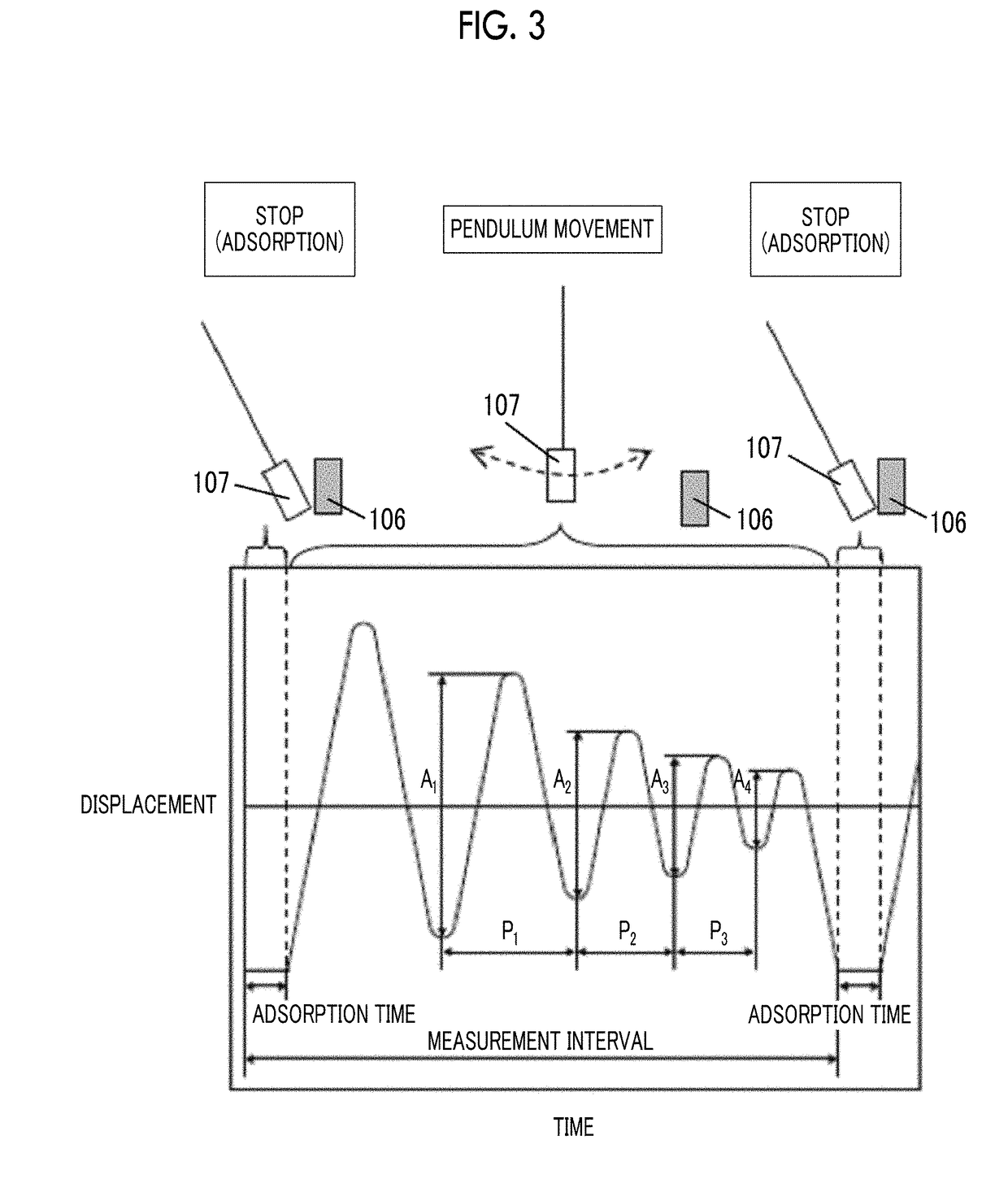
The magnetic tape includes a non-magnetic support; a magnetic layer including ferromagnetic powder and a binding agent on one surface side of the non-magnetic support; and a back coating layer including non-magnetic powder and a binding agent on the other surface side of the non-magnetic support, in which a thickness of the back coating layer is equal to or smaller than 0.30 μm, a logarithmic decrement acquired by a pendulum viscoelasticity test performed regarding the surface of the back coating layer is equal to or smaller than 0.060, and a contact angle with respect to 1-bromonaphthalene measured regarding a surface of the back coating layer is 15.0° to 30.0°.

Description

CROSS-REFERENCE TO RELATED APPLICATIONS[0001]This application claims priority under 35 U.S.C 119 to Japanese Patent Application No. 2017-029509 filed on Feb. 20, 2017. The above application is hereby expressly incorporated by reference, in its entirety, into the present application.BACKGROUND OF THE INVENTION1. Field of the Invention[0002]The present invention relates to a magnetic tape.2. Description of the Related Art[0003]Magnetic recording media are divided into tape-shaped magnetic recording media and disk-shaped magnetic recording media, and tape-shaped magnetic recording media, that is, magnetic tapes are mainly used for storage such as data back-up.[0004]As the magnetic tapes, JP1988-249932A (JP-S63-249932A) and JP1989-60819A (JP-H01-60819A) disclose a magnetic tape including a back coating layer (described as a “back layer” in JP1988-249932A (JP-S63-249932A) and JP1989-60819A (JP-H01-60819A)) on a surface side of a non-magnetic support opposite to a surface side provided wi...

Claims


Application Information

Patent Timeline
IPC IPC(8): G11B5/68G11B5/72
CPCG11B5/68G11B5/72G11B5/735G11B5/78
Inventor KASADA, NORIHITO
Owner FUJIFILM CORP
Learn More