Drive system with electromagnetic energy transfer

a technology of electromagnetic energy transfer and drive system, which is applied in the direction of synchronous motors, other domestic objects, transportation and packaging, etc., can solve the problems of complex and expensive solution for wireless transfer of electrical power to a moving vehicle, subject to wear and lead to maintenance needs, etc., and achieve the effect of improving the current sta

Active Publication Date: 2018-08-30
TETRA LAVAL HLDG & FINANCE SA
View PDF1 Cites 7 Cited by
  • Summary
  • Abstract
  • Description
  • Claims
  • Application Information

AI Technical Summary

Benefits of technology

This patent is about a device that uses magnetic energy to transfer power. The device includes a primary magnetic element, which is either a permanent magnet or an electromagnet. To reduce the energy needed, the primary magnetic element is preferably a permanent magnet. The movable element of the device has a slot made of high permeability material, such as iron, which houses the secondary magnetic element, which is a coil wound by a wire made of high electric conductivity material, such as copper wire. The slot helps collect and concentrate the magnetic flux energy generated by the windings of the secondary magnetic element, which makes the energy transfer from the sub-harmonic more efficient. The technical effect of this design is to improve the efficiency of power transfer with a smaller amount of energy.

Problems solved by technology

Brush connectors are however a mechanical solution that is subject to wear and leads to maintenance needs.
This solution for wireless transfer of electrical power to a moving vehicle is, however, complicated and expensive due to the need of a non-standard power-supply or the use of multiple power supplies for achieving the alternative current for moving the vehicles with a high frequency alternative current superimposed for transferring electrical power.

Method used


Image

  • Drive system with electromagnetic energy transfer
  • Drive system with electromagnetic energy transfer
  • Drive system with electromagnetic energy transfer

Examples


Embodiment Construction

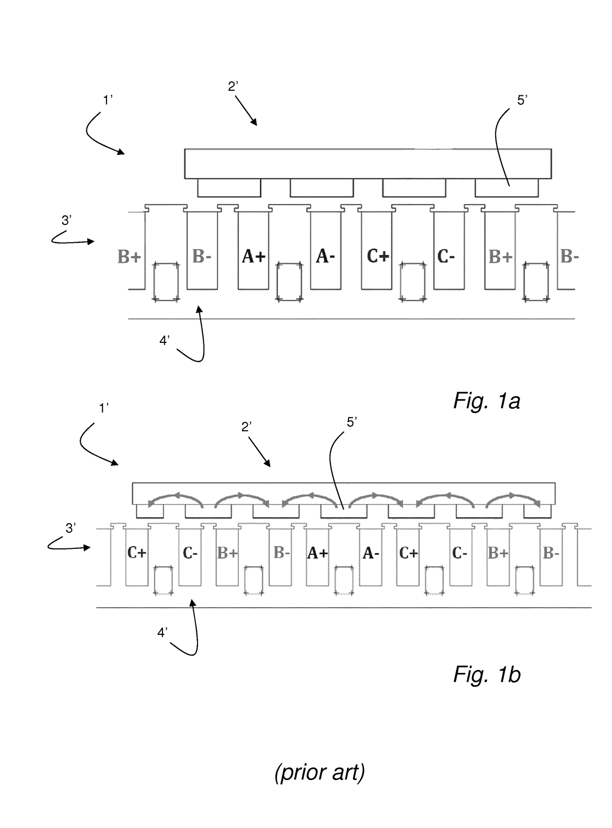
[0030]FIG. 1a and FIG. 1b show side views of a linear synchronous machine with a drive system according to known prior art. The drive system 1′ for movable elements 2′ comprises a track 3′ with a plurality of stators 4′, wherein each stator 4′ has a winding (not shown) fed with a current so as to generate a magnetic field and therefore a magnetic flux. The magnetic flux affects a magnetic element 5′ in the movable element 2′ so as to pull the movable element 2′ in a direction along said track 3′. The current that is fed to the stator windings is an alternating current, e.g. a sinusoidal current with three phases and with a frequency that controls the speed of the moving element 2′. In FIG. 1a and FIG. 1b the three phases are referenced as A, B and C. The phases A, B, C, are fed to succeeding stator windings in the drive system 1′ to accomplish a successive movement of the magnetic pull on the moving element 2′ and thereby a continuous movement of the moving element 2′.
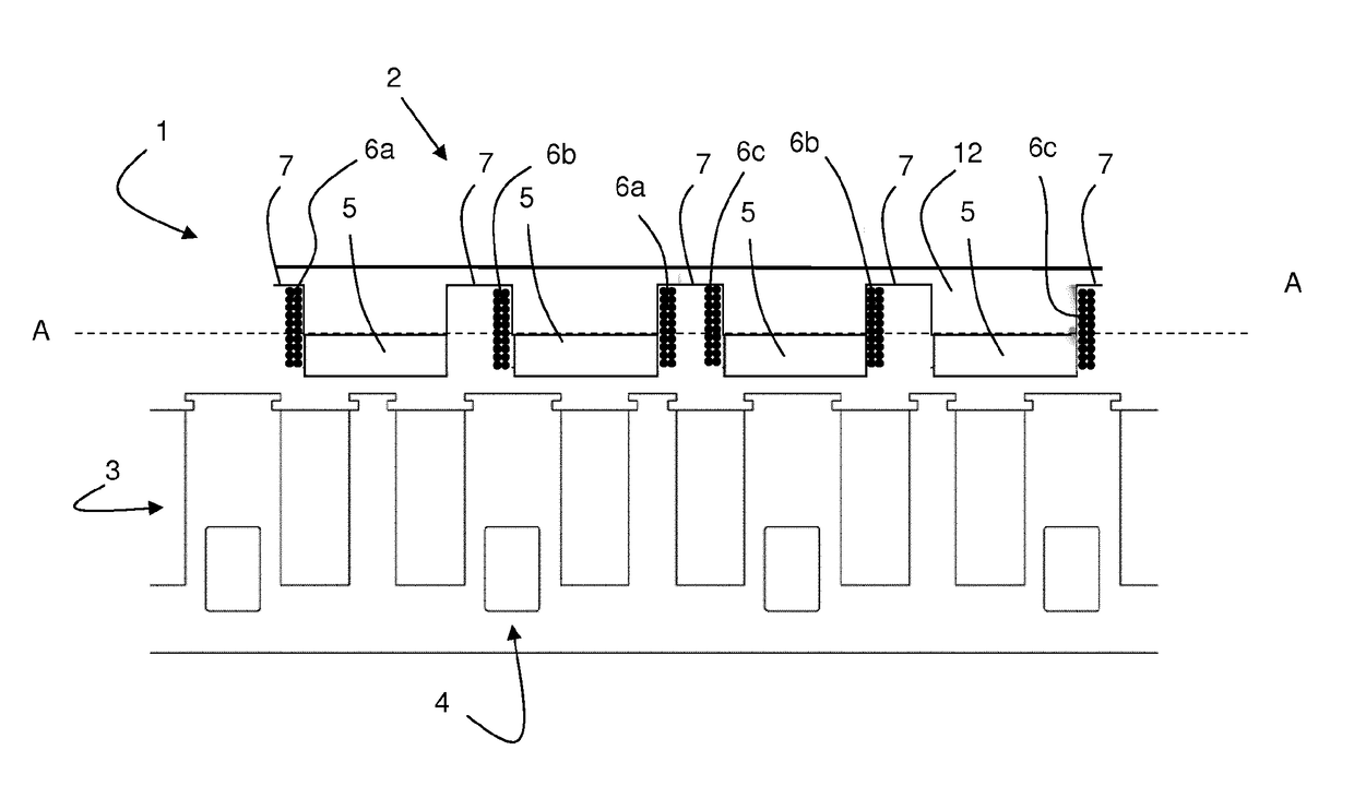
[0031]FIG. 2 i...


PUM


Abstract

The invention relates to a drive system (1) with electromagnetic energy transfer. The system (1) comprises a track (3) comprising a plurality of stators (4), each stator (4) having at least one winding adapted to generate a magnetic field having a fundamental harmonic (8) and at least one further harmonic (9) when fed with an varying current, and a movable element (2) comprising a primary magnetic element (5) adapted to receive said fundamental harmonic (8) to drive said movable element (2) along said track. The system (1) is characterized in that said movable element (2) further comprises a secondary magnetic element (6a-6c) adapted to receive said at least one further harmonic (9) to generate power onboard of said movable element (2). The invention also relates to a linear fractional slot synchronous machine and a rotational synchronous machine.

Description

TECHNICAL FIELD[0001]The invention relates to a drive system with electromagnetic energy transfer. The invention also relates to a linear fractional slot synchronous machine and a rotational synchronous machine. The aim is to do energy harvesting on board a movable element of a servo brushless motor in order to generate electrical power on the moving element for different usages, depending on application.BACKGROUND ART[0002]In the food packaging industry packages are manufactured and filled with food in large machines transforming packaging material into packages which are filled with food content, either during the formation of the package or after the package has been created. In these packaging machines, packages and equipment for handling the packages or the packaging material need to be conveyed.[0003]WO 2015 / 101492 discloses a solution for the problem of molding plastic objects onto cardboard-based packaging material intended to form packages while the packaging material is co...

Claims


Application Information

Patent Timeline
Patent Type & Authority Applications(United States)
IPC IPC(8): H02K41/03
CPCH02K41/033B60L13/03B29C66/849B29C66/8244B29C33/34B29L2031/712H02K41/03H02K19/12H02K19/28H02K41/031
Inventor BORGHI, DAVIDEFLORE, STEFANOBIANCHINI, CLAUDIODAVOLI, MATTEO
Owner TETRA LAVAL HLDG & FINANCE SA
Why Eureka
Try Eureka