Supercritical fluid dyeing and finishing system and method

a technology of supercritical fluid and dyeing system, applied in the direction of dyeing process, textile treatment by spraying/projecting, etc., can solve the problems of affecting the sustainable development of textile printing and dyeing industry, affecting the large amount of wastewater discharge becoming the primary challenge. , to achieve the effect of dissolution speed of dye, improving the dispersion speed of dye and/or

Active Publication Date: 2018-09-13
DALIAN POLYTECHNIC UNIVERSITY
View PDF0 Cites 4 Cited by
  • Summary
  • Abstract
  • Description
  • Claims
  • Application Information

AI Technical Summary

Benefits of technology

[0006]By the arrangement of a fabric warp beam dyeing and finishing unit, the present disclosure not only solves the problems of long time and low efficiency of batch supercritical CO2 fluid dyeing of the rope fabric, but also alleviates the problems of dyeing spots and fabric creases.
[0017]Another objective of the present disclosure is to provide a supercritical fluid dyeing and finishing method using the system, which includes the following steps: putting dye and / or a finishing agent in the dye drum, and enabling supercritical carbon dioxide fluid to flow to the dye drum from the inlet of the dye vat, then flow into the dye coil pipe, pass through a hole in the dye coil pipe and flow out from the outlet of the dye vat; enabling the supercritical carbon dioxide fluid in which the dye and / or the finishing agent is dissolved to enter from the inlet of the fabric warp beam dyeing kettle, then enter into the porous pipe I and the porous pipe II on the one hand to dye and finish a fabric wound thereon, such that the porous pipe I and the porous pipe II rotate under the action of the external magnetic transmission device II, the internal magnetic transmission device II and the internal magnetic transmission device III to realize dyeing and finishing of the single-layer fabric, and enter the fluid ejector on the other hand to realize directional dyeing and finishing of the fabric.
[0019](1) The porous coil pipe of the present disclosure can effectively increase the contact area between dye and CO2 fluid and improve the dispersibility of the dye and / or the finishing agent; meanwhile, the stirring device rotates axially in the dye vat and further improves the dispersion speed and the dissolution speed of the dye.
[0020](2) The fabric warp beam dyeing and finishing unit of the present disclosure realizes simultaneous winding as well as dyeing and finishing of the fabric and thus improves the dyeing and finishing speed under the action of the external magnetic transmission device II, the internal magnetic transmission device II and the internal magnetic transmission device III, and also achieves directional dyeing of the fabric by the fluid ejector and further increase the dyeing and finishing speed and improve the dyeing and finishing quality.

Problems solved by technology

With the widespread recognition of a low-carbon economic and a low-carbon development concept in various countries in the world, a large amount of wastewater discharge has become the primary challenge in the textile printing and dyeing industry.
China's textile industry is facing an extremely grim prospect in the low carbon economy.
According to incomplete statistics, the total amount of wastewater discharged by printing and dyeing enterprises in China reaches 3 to 4 million tons per day, COD and BOD are as high as 2000-3000 mg / L, residual dyes, heavy metals, sulfur compounds and various kinds of non-biodegradable organic additives in wastewater are difficult to be treated effectively by coagulation, filtration, adsorption and other methods, and therefore the wastewater discharged by printing and dyeing enterprises is one of industrial wastewaters which are most difficult to treat.
High dependence on water resources and high energy consumption, high emissions and other issues have seriously hampered the sustainable development of the textile printing and dyeing industry.
However, batch dyeing of fabric supercritical CO2 fluid still has the problems of long dyeing time and low dyeing efficiency.
In addition, supercritical CO2 fluid dyeing of a rope fabric can also cause the problems of dyeing spots and fabric creases.
The above problems have become the bottleneck restricting the industrialization application of batch supercritical CO2 fluid dyeing and finishing of fabrics.

Method used


Image

  • Supercritical fluid dyeing and finishing system and method
  • Supercritical fluid dyeing and finishing system and method
  • Supercritical fluid dyeing and finishing system and method

Examples


embodiment 1

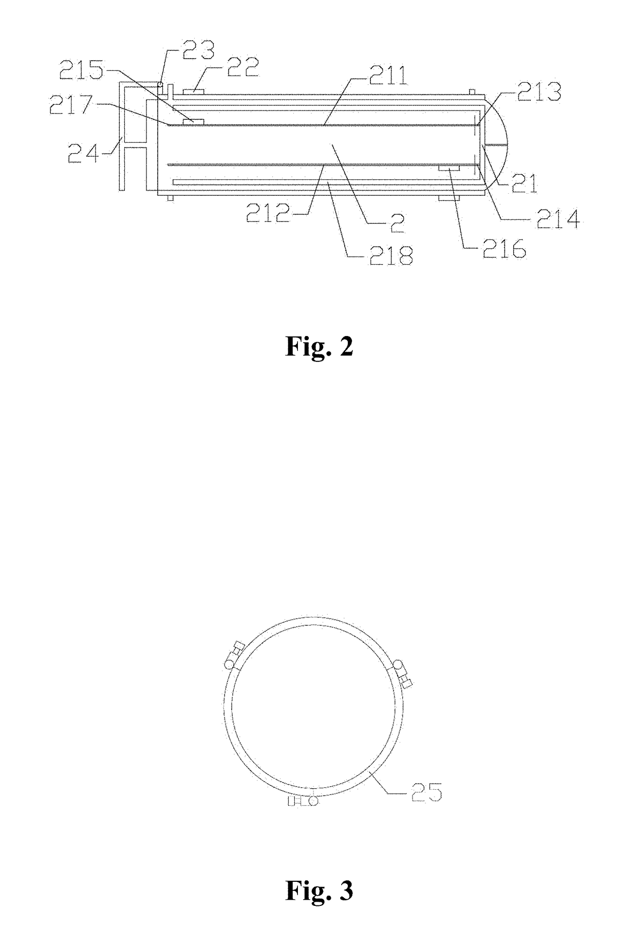
[0028]A supercritical fluid dyeing and finishing system includes a dye vat 1 which is connected with a fabric warp beam dyeing kettle 2.

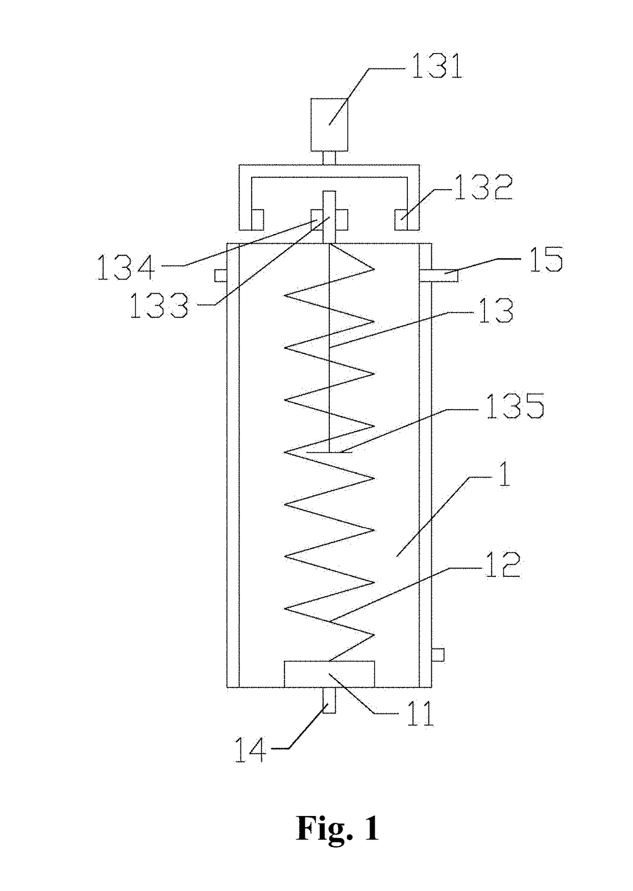
[0029]As shown in FIG. 1, the dye vat 1 includes a dye drum 11, a dye coil pipe 12 and a stirring device 13; an inlet of the dye vat 1 is sequentially connected with the dye drum 11, the dye coil pipe 12 and an outlet of the dye vat 1; the dye coil pipe 12 is of a gradient porous structure whose pore diameter increases gradually from 1 μm to 1 mm from bottom to top; the stirring device 13 includes a stirring motor 131, an external magnetic transmission device I 132, a transmission rod 133, an internal magnetic transmission device I 134, and stirring blades 135; the stirring motor 131 is connected with the external magnetic transmission device I 132 and distributed outside the dye vat 1; the transmission rod 133 passes through the dye vat 1 and is connected with the stirring blades 135 in the stirring kettle 1; a part of the transmission rod 133 outs...

embodiment 2

[0031]A supercritical fluid dyeing and finishing method using the system of Embodiment 1 includes the following steps:

[0032]putting disperse red 60 in the dyeing drum 11 in a proportion of 1 w / w %;

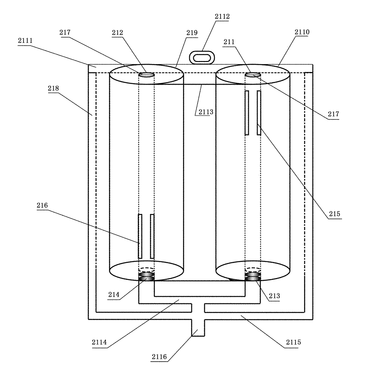
[0033]winding one end of a 1000 m Dacron fabric to the porous pipe I 211 and winding the other end thereof to the porous pipe II 212;

[0034]introducing supercritical carbon dioxide fluid to the dye drum 11 from an inlet of the dye vat 1 to dissolve dye, such that the dye is sufficiently dispersed and dissolved by the dye coil pipe 12 under the impact of the supercritical carbon diode fluid and enters into the dye vat 1 through holes in the dye coil pipe 12, wherein a stirring speed of the stirring blades 135 is 50 r / min; and enabling the supercritical carbon diode fluid in which the dye is dissolved to flow out from an outlet of the dye vat 1 and enter the fabric warp beam dyeing kettle 2 to perform dyeing at a temperature of 140° C. and a pressure of 24 MPa, wherein the supercritical carbo...

embodiment 3

[0036]A supercritical fluid dyeing and finishing method using the system of Embodiment 1 differs from Embodiment 2 in that:

[0037]disperse blue 79 is put in the dyeing drum 11 in a proportion of 0.5 w / w %;

[0038]one end of a 2000 m Dacron fabric is wound to the porous pipe I 211 and the other end thereof is wound to the porous pipe II 212;

[0039]The stirring speed of the stirring blades 135 is 100 r / min;

[0040]dyeing is performed at a temperature of 120° C. and a pressure of 26 MPa;

[0041]the porous pipe II 212 rotates for 20 min at a speed of 100 m / min;

[0042]When the stoppers 217 detect the remaining layer of the Dacron fabric, the internal magnetic transmission device II 215 stops moving and the internal magnetic transmission device II 216 begins to move, such that the Dacron fabric is rewound onto the porous pipe I 211.

[0043]Test results show that the dyeing K / S value of the dyed Dacron fabric is 16.8, and the standard deviation of the K / S value is lower than 0.02.


PUM

PropertyMeasurementUnit
pore diameteraaaaaaaaaa
speedaaaaaaaaaa
pressureaaaaaaaaaa

Abstract

A supercritical fluid dyeing and finishing system has a fabric warp beam dyeing kettle. A fabric warp beam dyeing and finishing unit is arranged in the fabric warp beam dyeing kettle. An external magnetic transmission device II is arranged outside the fabric warp beam dyeing kettle. The fabric warp beam dyeing and finishing unit includes a porous pipe I and a porous pipe II. The porous pipe I and the porous pipe II are connected with an inlet of the fabric warp beam dyeing and finishing unit through a bearing I and a bearing II. A fluid ejector is connected with the inlet of the fabric warp beam dyeing and finishing unit and disposed in the vicinity of the porous pipe I and the porous pipe II.

Description

TECHNICAL FIELD[0001]The present disclosure relates to a supercritical fluid dyeing and finishing system and method, belonging to the field of dyeing and finishing.BACKGROUND ART[0002]With the widespread recognition of a low-carbon economic and a low-carbon development concept in various countries in the world, a large amount of wastewater discharge has become the primary challenge in the textile printing and dyeing industry. China's textile industry is facing an extremely grim prospect in the low carbon economy. According to incomplete statistics, the total amount of wastewater discharged by printing and dyeing enterprises in China reaches 3 to 4 million tons per day, COD and BOD are as high as 2000-3000 mg / L, residual dyes, heavy metals, sulfur compounds and various kinds of non-biodegradable organic additives in wastewater are difficult to be treated effectively by coagulation, filtration, adsorption and other methods, and therefore the wastewater discharged by printing and dyein...

Claims


Application Information

Patent Timeline
Patent Type & Authority Applications(United States)
IPC IPC(8): D06P1/81D06B1/02D06B23/18D06B23/04D06B23/20
CPCD06B2700/36D10B2211/02D06B23/205D06P1/81D10B2401/22D06B23/18D06B23/042D10B2331/04D06B1/02D06B23/04D06B23/20D06B9/02D06B19/00D06B23/14D06P1/94
Inventor ZHENG, HUANDAZHENG, LAIJIUGAO, SHIHUIYAN, JUNZHANG, JUANWANG, XIAOMA, YINGCHONG
Owner DALIAN POLYTECHNIC UNIVERSITY
Why Eureka
Try Eureka