Field Programmable Logic Array

a logic array and field technology, applied in the field of field programmable logic arrays, can solve the problems of system shutdown, difficulty in developing asic for industrial control systems with a small number of production units,

Active Publication Date: 2018-09-27
HITACHI LTD
View PDF0 Cites 2 Cited by
  • Summary
  • Abstract
  • Description
  • Claims
  • Application Information

AI Technical Summary

Benefits of technology

[0022]According to the present invention, in a case where a system for which a high level of safety is demanded is realized using one SRAM-type FPGA including the hard macro, the system can be made to proceed into a safe state before influence of failure is transmitted to external equipment even if the FPGA fails.
[0023]Problems, configurations and effect except for the abovementioned ones will be clarified by description of the following embodiments.

Problems solved by technology

However, recently, it has been difficult to newly develop ASIC for an industrial control system having a small number of production units because of the rise of manufacturing costs according to refinement in a semiconductor process.
However, when temporary failure called a soft error that a bit of SRAM temporarily changes occurs due to this characteristic by influence of noise from the outside, cosmic rays radiated in the air and the like, the configuration is turned into a configuration different from a desired circuit, consequently, a malfunction of a system is caused, and a case where a system is shut down may occur.

Method used


Image

  • Field Programmable Logic Array
  • Field Programmable Logic Array
  • Field Programmable Logic Array

Examples


first embodiment

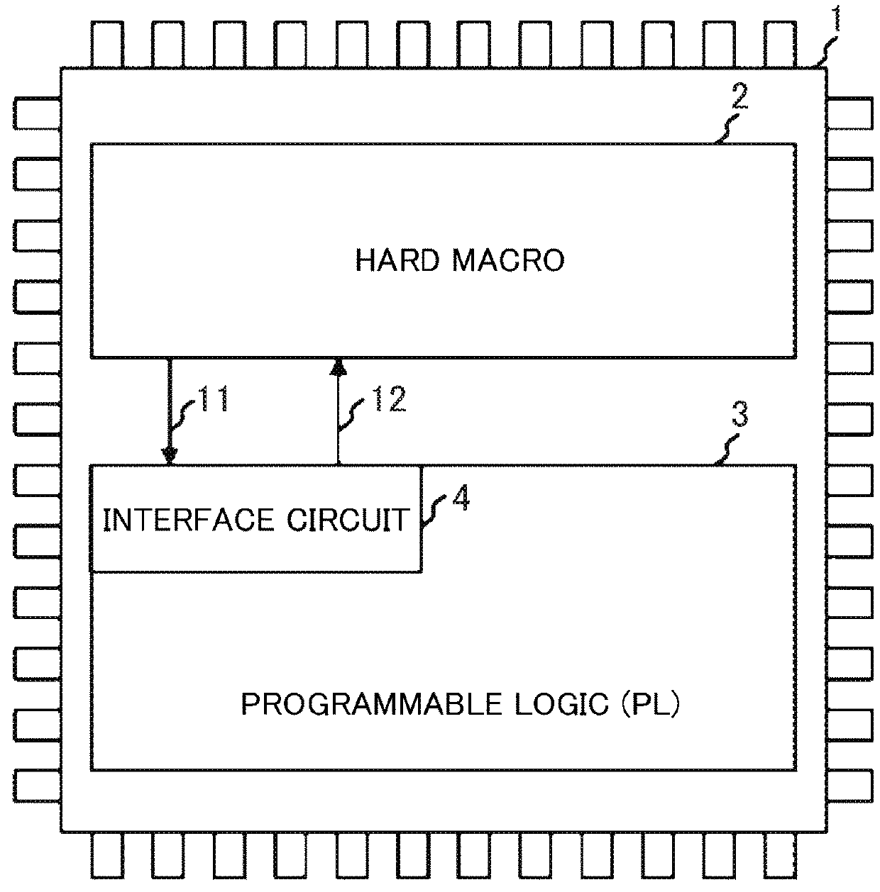
[0038]FIG. 1 shows one example of a general view showing FPGA according to the present invention.

[0039]The FPGA (1) has the following configuration. A hard macro 2 the circuitry configuration of which is fixed and the function of which cannot be changed and a programmable logic (PL) 3 the circuitry configuration of which can be changed when power is turned on and in operation are built in the FPGA, an interface circuit 4 is built in the PL (3), the hard macro 2 outputs a PL diagnosis control signal 11 to the interface circuit 4, and the interface circuit 4 outputs a PL data signal 12 acquired by hardware operation process of the PL (3) to the hard macro 2. The hard macro 2 and the PL (3) are packaged with an area between them, and only the PL diagnosis control signal 11 and the PL data signal 12 are communicated between the hard macro and the PL.

[0040]As described above, failure of the PL (3) can be prevented from having an effect on the hard macro by packaging the hard macro 2 and ...

second embodiment

[0056]Next, an example of a case where a further high level of safety is realized in a system using the field programmable logic array according to the present invention will be described.

[0057]Time charts shown in FIG. 5 are different from the time charts shown in FIG. 4 in that PL diagnosis processing 52 is located at the head of each control cycle in all of (a), (b), (c).

[0058]RT processing is executed only when failure of a PL part is not detected by executing the PL diagnosis processing 52 at the beginning of the control cycle.

[0059]As described above, a safe operational state can be maintained as the system in units of control cycles by executing the PL diagnosis processing at the beginning of the control cycle.

third embodiment

[0060]Next, one example of a case where a further higher level of safety is realized without outputting incorrect data to the outside of FPGA in the field programmable logic array according to the present invention will be described referring to FIGS. 6 and 7.

[0061]The FPGA (301) shown in FIG. 6 is different from the FPGA (1) shown in FIG. 1 in that comparators 305, 306 are installed in a hard macro 302 and in that arithmetic circuits 303, 304 are installed in a part of PL (3).

[0062]In this case, the arithmetic circuits 303, 304 have the same function.

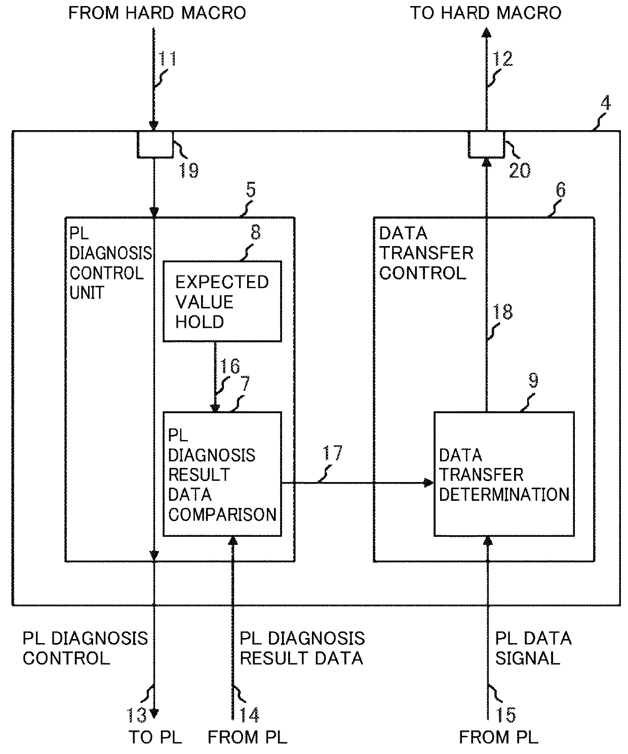
[0063]In addition, an interface circuit 307 shown in FIG. 7 is different from the interface circuit 4 shown in FIG. 2 in that another set of data transfer determination equipment 332 and an output port 333 are installed in a data transfer control unit 331.

[0064]The data transfer determination equipment 332 inputs a PL data signal 322 from the arithmetic circuit 304 and controls a value of a PL data signal 324 to be output to the hard m...


PUM


Abstract

To realize control of a system for which a high level of safety is demanded by one SRAM-type FPGA, it is to eliminate a possibility that an undesirable control signal is output to the outside of the FPGA because of influence of failure by a soft error and the like and a problem. To solve this problem, there is provided a hard macro having fixed circuitry structure, programmable logic arranged via an interval close to the hard macro and having a changeable circuitry structure, and an I/F circuit which is provided inside the programmable logic and outputs a processing result in the programmable logic to the hard macro. It is a characteristic that the I/F circuit monitors soundness of the programmable logic and stops output of the processing result to be transmitted to the hard macro on the basis of a monitoring result.

Description

TECHNICAL FIELD[0001]The present invention relates to a field programmable logic array.BACKGROUND ART[0002]In a control system for which very high reliability is demanded so as to ensure safety of a human life and environment for a plant, a railroad, an automobile, an airplane and the like, in case failure and abnormality should occur in the system, measures for preventing the system from running out of control and running into a dangerous situation are required to be taken.[0003]Therefore, for a controller that controls inside such a system, reliability and safety are required to be enhanced.[0004]For such a controller, an ASIC (Application Specific Integrated Circuit) has been principally used.[0005]However, recently, it has been difficult to newly develop ASIC for an industrial control system having a small number of production units because of the rise of manufacturing costs according to refinement in a semiconductor process.[0006]In the meantime, as to a Field Programmable Logi...

Claims


Application Information

Patent Timeline
Patent Type & Authority Applications(United States)
IPC IPC(8): H03K19/177G06F11/10G11C29/52G01R31/317
CPCH03K19/17764G06F11/1068G11C29/52G06F11/1004G01R31/31703
Inventor SAKATA, TERUAKIYAMADA, TSUTOMUHIROTSU, TEPPEI
Owner HITACHI LTD
Why Eureka
Try Eureka