Self-Shielded Image Guided Radiation Oncology System

a radiation oncology and self-shielding technology, applied in radiation therapy, medical science, radiation therapy, etc., can solve the problems of unpopular product combinations, high cost, and difficulty in integrating high-quality fan beam ct scanning or mri into a linear accelerator system, so as to reduce the overall system utilization factor, reduce the total area required for shielding, and increase the effective dose rate at the isocenter

Active Publication Date: 2018-10-04
ETM ELECTROMATIC
View PDF1 Cites 11 Cited by
  • Summary
  • Abstract
  • Description
  • Claims
  • Application Information

AI Technical Summary

Benefits of technology

[0020]For a conventional vault design, a primary shielding barrier covers all possible intercepts of the projected primary radiation field with the vault and therefore often requires a thickened “primary shielding belt” on the treatment room walls and the center portion of the ceiling. In the present invention, the X-ray source is designed so that this primary shielding belt can be positioned closer to the patient with the result that the total area required shielding is greatly reduced. An additional benefit provided by the use of a smaller radiation-source-to-isocenter distance than conventional linear accelerator systems is that the effective dose rate at the isocenter will increase. This permits a corresponding decrease in the utilization factor of the overall system, which in turn permits decreasing the required thickness of the primary shielding belt. For example, in an embodiment, a radiation-source-to-isocenter distance of 85 centimeters can be used. Another benefit of the present design is that the size of the treatment field can be restricted to 25 cm×25 cm at isocenter, which further decreases the required width of the primary shielding belt provided by the arch and/or beam stop. Further, unlike robotic ...

Problems solved by technology

These imaging techniques provide some information, but at a generally lower image quality compared to dedicated fan beam CT scanners or MRI machines.
It is technologically challenging and expensive to incorporate high quality fan beam CT scanning or MRI into a linear accelerator system.
These product combinations have proven unpopular, perhaps because of the expense of not only the machine, but also the need to create a special new vault for shielding medical personnel.
Radiation therapy systems generate multiple sources of unwanted radiation are produced that provide a threat to operators, workers in adjacent areas, and the public.
Because of the cost of such conventional systems, including the vault or bunker, the availability of these devices is limited.
Typically, only large hospitals are able to utilize these devices often enough to justify the costs of offering such radiotherapy services.
This, in turn, restricts the availability of these devices to highly populated areas.
In such instances, patients requiring radiotherapy treatment frequently are required to travel significant distances to receive their...

Method used


Image

  • Self-Shielded Image Guided Radiation Oncology System
  • Self-Shielded Image Guided Radiation Oncology System
  • Self-Shielded Image Guided Radiation Oncology System

Examples


Embodiment Construction

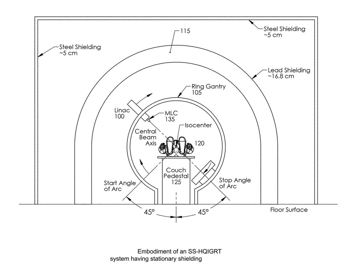
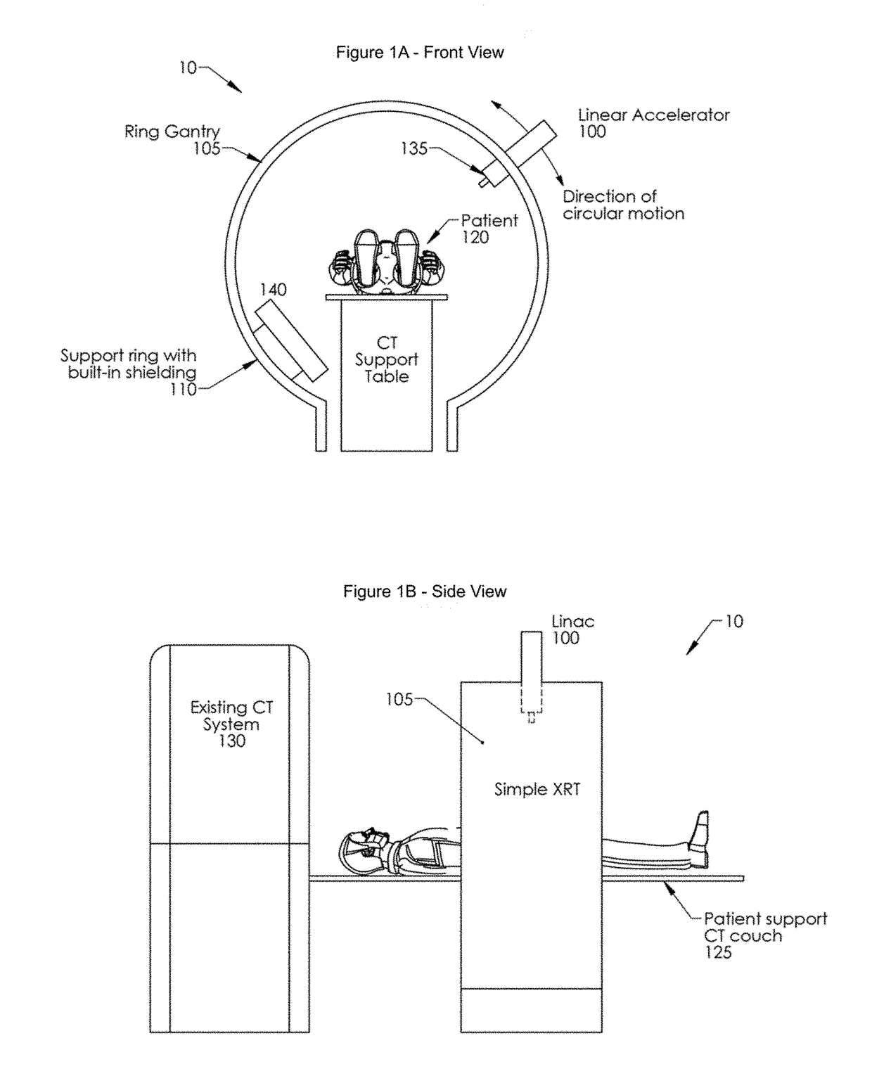
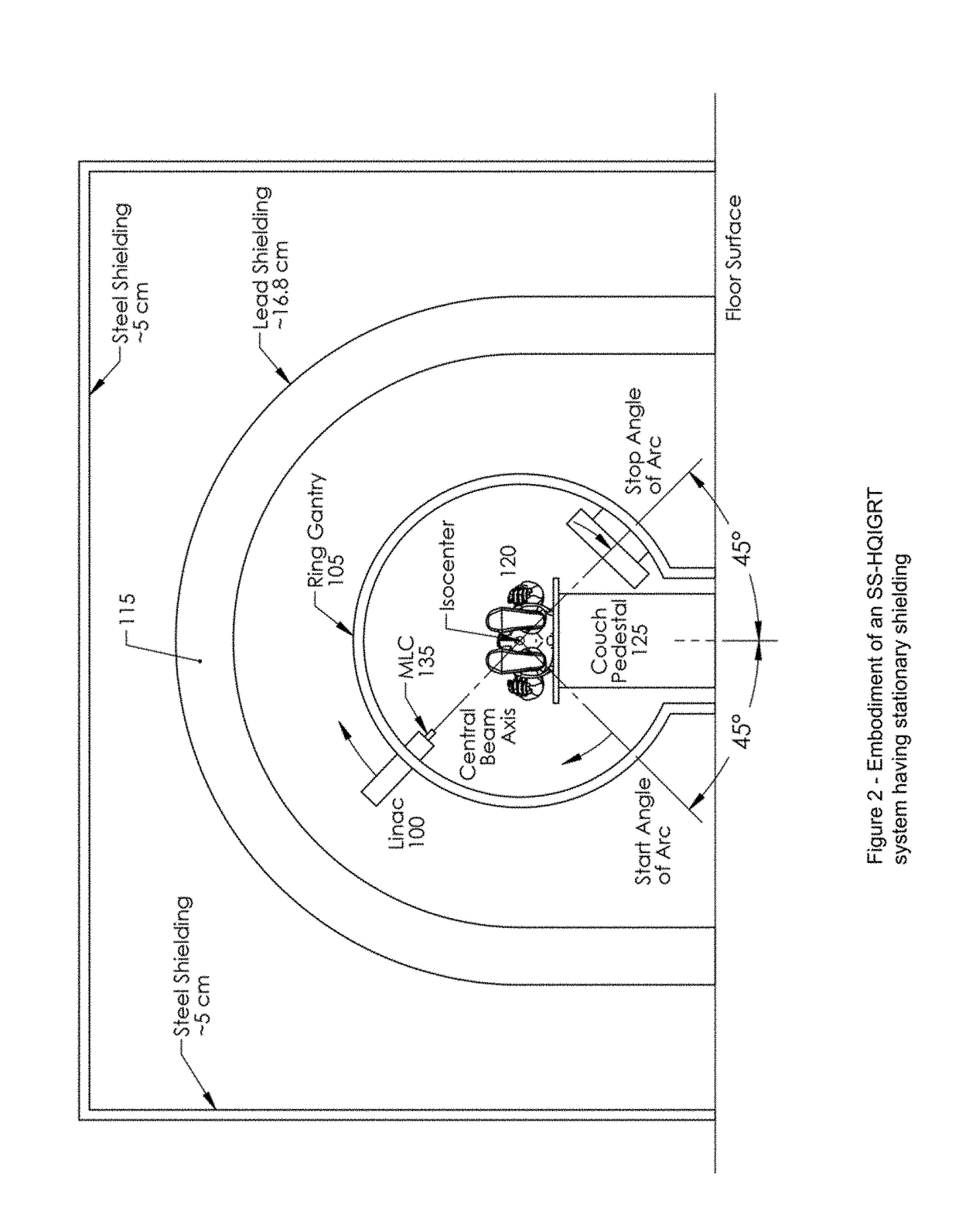
[0034]Referring first to FIGS. 1A-1B and 2, an embodiment of an SS X-ray source 10 in accordance with the present invention can be better appreciated. A linear accelerator, or linac, 100 moves around a ring gantry 105. Shielding 110 can be incorporated around the ring gantry as shown in FIG. 1A, or can be a separate arch 115 as shown in FIG. 2. The patient 120 is positioned on the CT support table, or couch, 125, and the CT imager 130 is positioned adjacent the SS X-ray source. The Linac 100 is mounted isocentrically within the ring gantry 105 and is able to rotate almost a full rotation of 360 deg. In at least some embodiments, a multi-leaf collimator 135 is incorporated into the treatment head containing the linac 100. Further, in at least some embodiments, a beam stop 140 is positioned diametrically opposite the linac 100 and rotates with the linac to provide shielding.

[0035]In at least some embodiments, the weight of the primary beam stop 140 is nearly the same weight as that of...


PUM


Abstract

An image-guided radiotherapy system adapted to be juxtaposed adjacent a CT scanner comprises a frame having an orifice adapted to permit passage therethrough of a couch on which a patient is positioned, together with a gantry assembly rotatably mounted on the frame in which the gantry assembly comprises a shielding cylinder having an orifice therethrough in alignment with the orifice in the frame. The shielding cylinder has affixed thereto a linac-based treatment head configured to provide radiotherapy, and a beamstop positioned angularly opposite the treatment head to absorb radiation from the treatment head. The shielding cylinder provides sufficient shielding of radiation scattered from the patient and the remainder of the system to not require a conventional vault. In some embodiments an arch may be used instead of a cylinder.

Description

RELATED APPLICATIONS[0001]This application is a conversion of U.S. Patent Application Ser. No. 62 / 265,130, filed Dec. 9, 2015, and further is a continuation in part of PCT Application Ser. No. PCT / US15 / 18164 filed Feb. 27, 2015, and U.S. patent application Ser. No. 14 / 634,361, filed Feb. 27, 2015, which are in turn continuations-in-part of U.S. patent application Ser. No. 14 / 192,864, filed Feb. 27, 2014, all of which are incorporated herein by reference.FIELD OF THE INVENTION[0002]The present invention relates generally to radiation oncology treatment systems, and more particularly relates to radiotherapy systems that are self-shielding while capable of treating a large percentage of cancers. In an additional aspect, the present invention relates to radiotherapy systems which combine high resolution imagers, such as fan beam CT imagers, with linac-based X-ray systems.BACKGROUND OF THE INVENTION[0003]State-of-the-art in radiation oncology treatments use 6 MeV to 20 MeV X-ray doses fr...

Claims


Application Information

Patent Timeline
IPC IPC(8): A61N5/10
CPCA61B6/4078A61B6/032A61N5/1081A61N5/1049A61N2005/1094A61N2005/1061A61N2005/005A61B6/50A61B6/0487
Inventor WEIDLICH, GEORGNIGHAN, WILLIAM L.DORE, DENNIS
Owner ETM ELECTROMATIC
Why Eureka
Try Eureka