Magnetic Transformer Having Increased Bandwidth for High Speed Data Communications

a high-speed data communication and transformer technology, applied in the direction of transformers/inductances, magnetic cores, fixed transformers or mutual inductances, etc., can solve the problems of less than ideal voltage regulation, leakage flux, and non-ideal operating characteristics, and achieve the effect of enhancing coupling

Active Publication Date: 2018-10-04
BEL FUSE MACAO COMML OFFSHORE
View PDF7 Cites 1 Cited by
  • Summary
  • Abstract
  • Description
  • Claims
  • Application Information

AI Technical Summary

Benefits of technology

[0009]In view of the foregoing, a need exists for a system and method that provides enhanced coupling between the windings of an isolation transformer in a high speed data communications coupler system.

Problems solved by technology

This non-ideal operating characteristic is known as leakage inductance.
Leakage inductance is caused by an imperfect coupling of the windings, which creates a leakage flux that does not link with all the turns of the secondary transformer windings.
As a result, the voltage drops across the leakage reactance of the circuit resulting in a less than ideal voltage regulation, especially when the transformer is placed under load.
This is particularly problematic in high frequency applications where the high frequency of the electrical current exacerbates the non-ideal parasitic effects seen in the transformer.
However, while it is possible to implement a combination of twisting and interleaving, twisting is often extremely difficult to accomplish when interleaving more than one set of windings.
This is often difficult to achieve when using both interleaving in combination with wire twisting.
In some configurations, the bunching of the wires may cause the start of a particular winding to be positioned near the finish of the particular winding, which may increase the parasitic capacitance between the start and the finish of the winding.

Method used


Image

  • Magnetic Transformer Having Increased Bandwidth for High Speed Data Communications
  • Magnetic Transformer Having Increased Bandwidth for High Speed Data Communications
  • Magnetic Transformer Having Increased Bandwidth for High Speed Data Communications

Examples


Embodiment Construction

[0037]An improved high data rate isolation transformer is disclosed in the attached drawings and is described below. The embodiment is disclosed for illustration of the transformer and is not limiting except as defined in the appended claims.

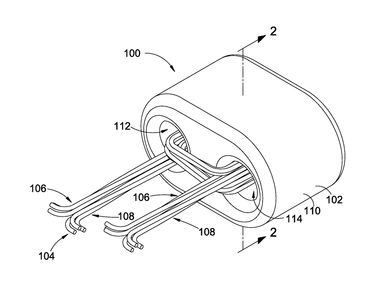
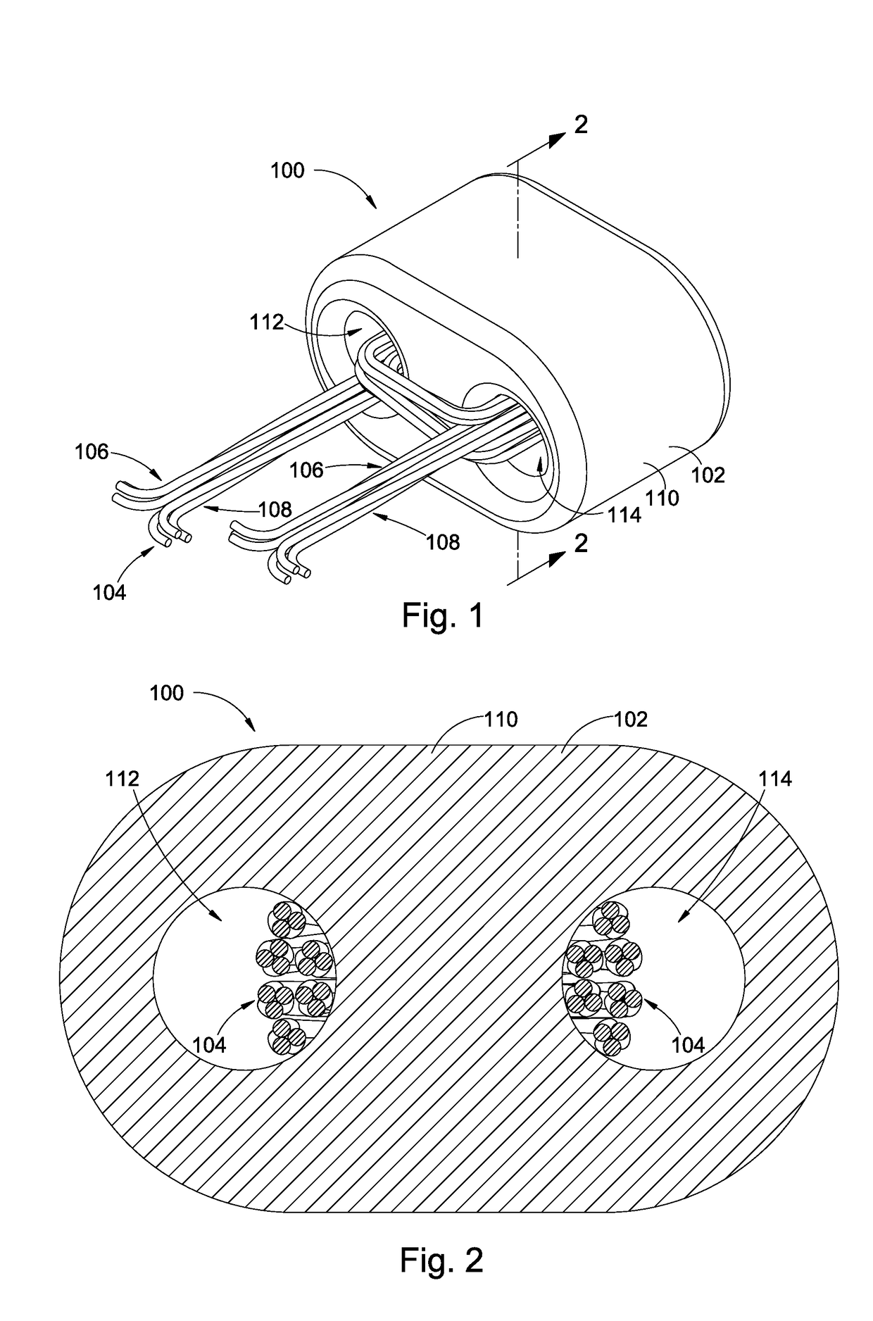
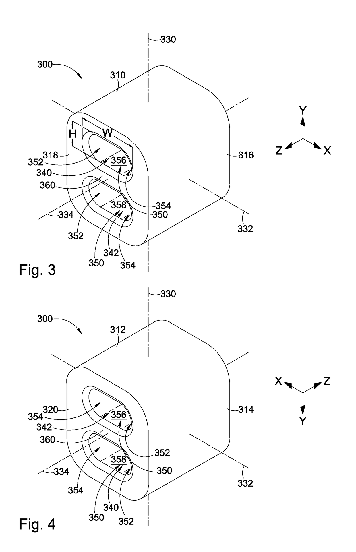
[0038]FIGS. 3 and 4 illustrate a transformer core 300 in accordance with a disclosed implementation. Unlike the core of the previously described oval-shaped transformer 100 of FIGS. 1 and 2, the transformer core 300 in FIGS. 3 and 4 has an overall box-like (parallelepiped) appearance having six generally rectangular sides. In the illustrated orientation referenced to X, Y and Z coordinates, the core has a top surface 310, a bottom surface 312, a left surface 314, a right surface 316, a front surface 318 and a rear surface 320. A first (top-bottom) central axis 330 passes through the center of the core from the top surface to the bottom surface parallel to the Y axis. A second (left-right) central axis 332 passes through the center of the core fr...


PUM

PropertyMeasurementUnit
frequencyaaaaaaaaaa
thicknessaaaaaaaaaa
widthaaaaaaaaaa

Abstract

An isolation transformer includes a transformer core. First and second through-bores extend through the transformer core from a first surface to a second surface. Each through-bore has an elongated profile with at least a portion of the elongated profile providing a respective flat winding surface. The flat winding surfaces are spaced apart by a central portion of the transformer core. The transformer is wound with a six-wire cable having a central non-conductive core. First, second, third, fourth, fifth and sixth conductive wires are positioned around and adjacent to the central non-conductive core in a substantially equally spaced angular relationship. The second conductive wire is positioned between the first conductive wire and the third conductive wire; and the fifth conductive wire is positioned between the fourth conductive wire and the sixth conductive wire. The conductive wires are twisted about the central non-conductive core at a selected twist density.

Description

RELATED APPLICATION[0001]The present application claims the benefit of priority under 35 USC § 119(e) to U.S. Provisional Application No. 62 / 480,757, filed on Apr. 3, 2017, which is incorporated by reference herein in its entirety.BACKGROUND OF THE INVENTIONField of the Invention[0002]This application is directed to conductors and circuit elements for use in high speed data communications, and, more particularly, to improvements in baluns and twisted wire cables.Description of the Related Art[0003]Transformers are devices that transfer electrical energy from one electrical circuit to another electrical circuit through the use of inductively coupled conductors. As is well understood, a varying current in a primary winding creates a varying magnetic flux and thus a varying magnetic field through a secondary winding. This varying magnetic field induces a varying electromotive force (“EMF”) or voltage in the secondary winding. An ideal transformer assumes that all the magnetic flux gene...

Claims


Application Information

Patent Timeline
Patent Type & Authority Applications(United States)
IPC IPC(8): H01F38/14H01F27/28H01F27/24H01F27/29
CPCH01F38/14H01F27/2823H01F27/24H01F27/29H01F19/06H01F41/08H01F2017/067H01F2019/085H01F41/07
Inventor RENTERIA, VICTOR H.LEUNG, WAI SHUN
Owner BEL FUSE MACAO COMML OFFSHORE
Why Eureka
Try Eureka