System to Pump Fluid and Control Thereof

a technology of actuators and fluid pumps, which is applied in the direction of positive displacement liquid engines, piston pumps, liquid fuel engines, etc., can solve the problems of inefficiency of hydraulic pumping at full speed or at some other constant speed, inability to precisely control the flow in the system, and prior art pumps in such industrial machines are not very responsive to changes in flow demand, etc., to achieve faster and more precise control of fluid flow and/or pressure, and reduce the size of accumulators

Active Publication Date: 2018-10-11
PROJECT PHOENIX
View PDF16 Cites 18 Cited by
  • Summary
  • Abstract
  • Description
  • Claims
  • Application Information

AI Technical Summary

Benefits of technology

[0008]Preferred embodiments of the present invention provide for faster and more precise control of the fluid flow and / or pressure in systems that use a variable-speed and / or a variable-torque pump. The fluid pumping system and method of control thereof discussed below are particularly advantageous in a closed-loop type system since the faster and more precise control of the fluid flow and / or the pressure in such systems can mean smaller accumulator sizes and a reduced risk of pump cavitation than in conventional systems. In an exemplary embodiment, a fluid system includes a variable-speed and / or a variable-torque pump, at least one proportional control valve assembly, an actuator that is operated by the fluid to control a load, and a controller to concurrently establish a speed and / or torque of the pump and an opening of the at least one proportional control valve assembly. The pump includes at least two fluid drivers that provide fluid to the actuator, which can be, e.g., a fluid-actuated cylinder, a fluid-driven motor or another type of fluid-driven actuator that controls a load (e.g., a boom of an excavator, a load attached to a hydrostatic transmission, or some other equipment or device that can be operated by an actuator). As used herein, “fluid” means a liquid or a mixture of liquid and gas containing mostly liquid with respect to volume. Each fluid driver includes a prime mover and a fluid displacement assembly. The fluid displacement assembly can be driven by the respective prime mover such that fluid is transferred from the inlet port to the outlet port of the pump. In some embodiments, a proportional control valve assembly is disposed between the pump outlet and an inlet port of the actuator. The proportional control valve assembly can include a proportional control valve and a valve actuator. In some embodiments, the proportional control valve assembly is disposed between an outlet port of the actuator and the pump inlet. In other embodiments, the system includes two proportional control valve assemblies with one valve assembly disposed between the pump outlet and actuator inlet port and the other valve assembly disposed between the actuator outlet port and the pump inlet. The controller concurrently establishes a speed and / or a torque of the prime movers and an opening of at least one proportional control valve so as to control a flow and / or a pressure in the fluid system.

Problems solved by technology

Typically, the inertia of the hydraulic pump in the above-described industrial applications makes it impractical to vary the speed of the hydraulic pump to precisely control the flow in the system.
That is, the prior art pumps in such industrial machines are not very responsive to changes in flow demand.
However, running the hydraulic pump at full speed or at some other constant speed is inefficient as it does not take into account the true energy input requirements of the system.
In addition, the flow control devices in these systems typically use hydraulic controls to operate, which can be relatively complex and require additional hydraulic fluid to function.
Because of the complexity of the hydraulic circuits and controls, these hydraulic systems are typically open-loop in that the pump draws the hydraulic fluid from a large fluid reservoir and the hydraulic fluid is sent back to the reservoir after performing work on the hydraulic actuator and after being used in the hydraulic controls.
To interconnect these parts, various additional components like connecting shafts, hoses, pipes, and / or fittings are used in a complicated manner and thus susceptible to contamination.
Moreover, these components are susceptible to damage or degradation in harsh working environments, thereby causing increased machine downtime and reduced reliability of the machine.
Thus, known systems have undesirable drawbacks with respect to complexity and reliability of the systems.
The '589 application, however, does not disclose a control scheme in which a pump control circuit, having at least one of a pressure control module and a flow control module, provides a demand signal to one of the fluid drivers of the pump that is greater in magnitude than a demand signal to the other fluid drivers to more precisely control the flow and pressure.

Method used


Image

  • System to Pump Fluid and Control Thereof
  • System to Pump Fluid and Control Thereof
  • System to Pump Fluid and Control Thereof

Examples


embodiment 1

2. The hydraulic system of embodiment 1, wherein the controller includes a plurality of operational modes including at least one of a flow control mode, a pressure control mode, and a balanced control mode.

embodiment 2

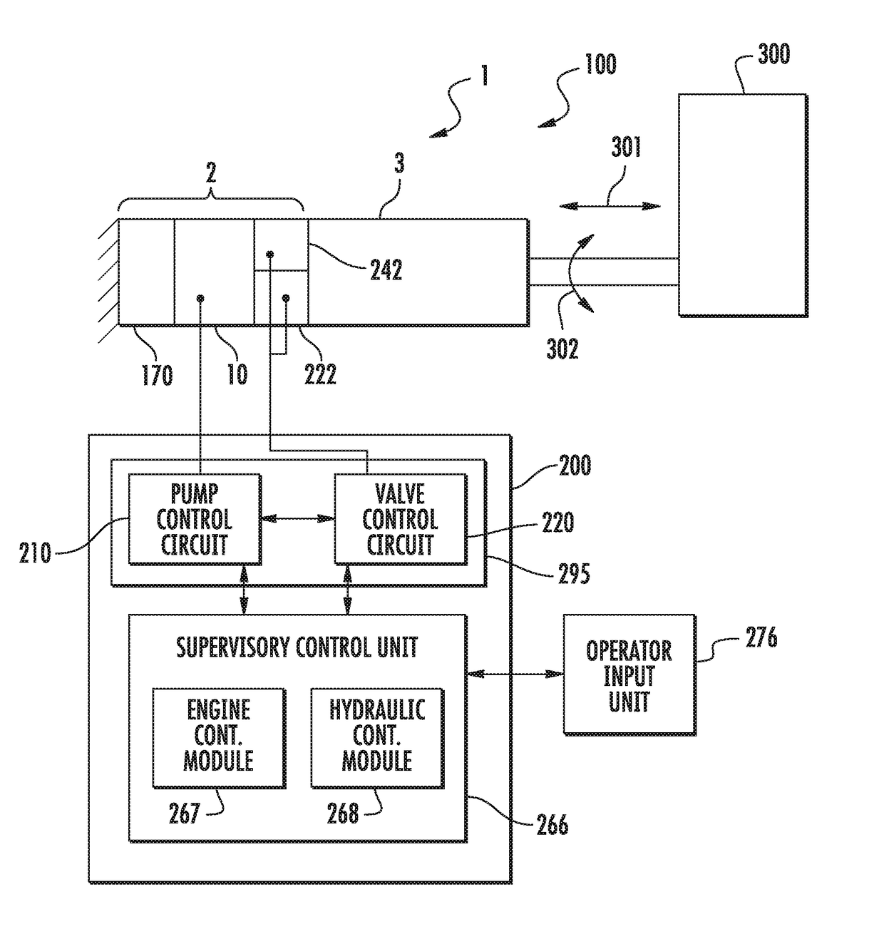
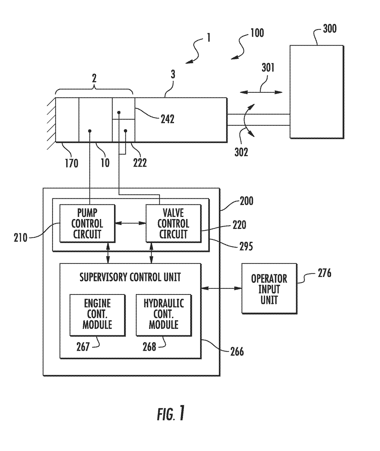
3. The hydraulic system of embodiment 2, wherein, in the balanced control mode, the pump control circuit controls the first and second motors to adjust the pressure in the system to the pressure set point and the valve control circuit concurrently controls the control valve to adjust the flow in the system to the flow set point.

4. The hydraulic system of embodiment 2, wherein, in the pressure control mode, the pump control circuit controls the first and second motors to adjust the pressure in the system to the pressure set point and the valve control circuit concurrently controls the control valve to adjust the pressure in the system to the pressure set point.

5. The hydraulic system of embodiment 2, wherein, in the flow control mode, the pump control circuit controls the first and second motors to adjust the flow in the system to the flow set point and the valve control circuit concurrently controls the control valve to adjust the flow in the system to the flow set point.

6. The hydr...

embodiment 7

8. The hydraulic system of embodiment 7, wherein the hydraulic system s a closed-loop system.

9. The hydraulic system of any one of embodiments 1 to 8, further comprising:[0178]a second control valve assembly including,[0179]a second control valve disposed on a side of the inlet port with respect to the direction of fluid flow, the second control valve in fluid communication with the second port and the inlet port, and[0180]a second control valve actuator to operate the second control valve,[0181]wherein the controller establishes the opening of the control valve and an opening of the second control valve to adjust the at least one of the flow to the flow set point and the pressure to the pressure set point.

10. The hydraulic system of any one of embodiments 1 to 9, further comprising:[0182]at least one of a pressure transducer, a temperature transducer, and a flow transducer.

11. The hydraulic system of any one of embodiments 1 to 10, wherein the first and second valves are ball valve...


PUM


Abstract

A fluid-driven actuator system includes a fluid-driven actuator and at least one proportional control valve and at least one pump connected to the fluid-driven actuator to provide fluid to operate the fluid-driven actuator. The at least one pump includes at least one fluid driver having a prime mover and a fluid displacement assembly to be driven by the prime mover such that fluid is transferred from the pump inlet to the pump outlet. The fluid driven actuator system also includes a controller that establishes at least one of a speed and a torque of the at least one prime mover to adjust at least one of a flow in the fluid system to a flow set point and a pressure in the fluid system to pressure set point and a concurrently establishes an opening of the at least one proportional control valve to adjust at least one of the flow to the flow set point and the pressure to the pressure set point.

Description

PRIORITY[0001]The present application is an international application claiming the benefit of priority to U.S. Provisional Application No. 62 / 213,524 filed on Sep. 2, 2015, which is incorporated herein by reference in its entirety.TECHNICAL FIELD[0002]The present invention relates generally to fluid pumping systems fluid-driven actuator assemblies and control methodologies thereof, and more particularly to fluid-driven actuator assemblies having at least one pump assembly, at least one proportional control valve assembly and a fluid-driven actuator; and control methodologies thereof in a fluid pumping system, including adjusting at least one of a flow and a pressure in the system by establishing a speed and / or torque of each prime mover in the at least one pump assembly and concurrently establishing an opening of at least one control valve in the at least one proportional control valve assembly.BACKGROUND OF THE INVENTION[0003]Fluid-driven actuator assemblies are widely used in a va...

Claims


Application Information

Patent Timeline
Patent Type & Authority Applications(United States)
IPC IPC(8): F04C14/08F15B15/18F04C2/18F04C14/02F04C14/24
CPCF04C14/08F15B15/18F04C2/18F04C14/02F04C14/24F04C2240/811F04C2270/035F04C2270/0525F04C2270/605F04C2270/185F04C2270/205F04C2240/402F04C2270/19F15B1/26F01C1/18F04B9/105F03C1/0607F04C11/008
Inventor AFSHARI, THOMAS
Owner PROJECT PHOENIX
Why Eureka
Try Eureka