Focussing of gratings for differential phase contrast imaging by means of electro-mechanic transducer foils

a technology of electro-mechanic transducer foil and differential phase contrast, which is applied in the direction of imaging devices, nuclear engineering, and diaphragm/collimeter handling, etc., can solve the problem that the grating structure remains substantially undisturbed, and achieve the effect of reducing shadowing effects

Inactive Publication Date: 2018-10-11
KONINKLJIJKE PHILIPS NV
View PDF7 Cites 3 Cited by
  • Summary
  • Abstract
  • Description
  • Claims
  • Application Information

AI Technical Summary

Benefits of technology

[0004]There may therefore be a need to reduce ...

Problems solved by technology

In other words, this allows bending or tilting only the ridges (or parts there...

Method used


Image

  • Focussing of gratings for differential phase contrast imaging by means of electro-mechanic transducer foils
  • Focussing of gratings for differential phase contrast imaging by means of electro-mechanic transducer foils
  • Focussing of gratings for differential phase contrast imaging by means of electro-mechanic transducer foils

Examples


Embodiment Construction

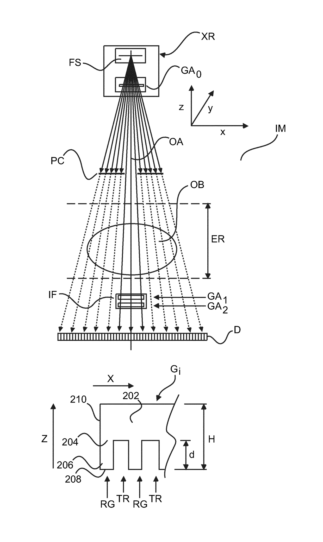
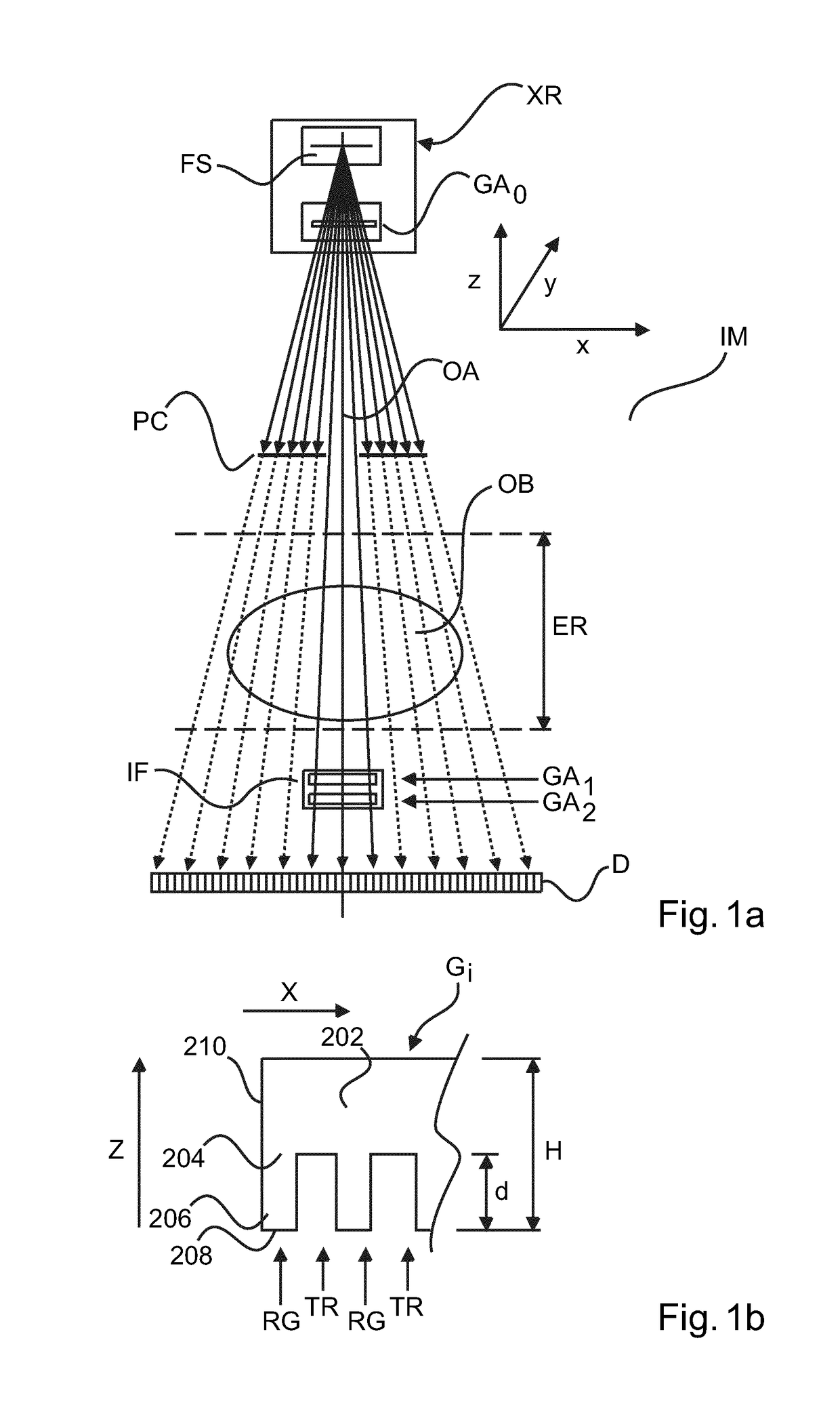
[0048]Panel a) of FIG. 1 affords a schematic side elevation view of an X-ray imaging apparatus IM. The X-ray imaging apparatus comprises an X-ray source XR and a radiation sensitive detector D arranged across an examination region ER opposite said source XR. Preferably, but not necessarily, the X-ray detector D is 2D (two-dimensional). In other words, the X-ray detector is a “true” 2D structure where a plurality of detector pixels are arranged in rows and columns as an array to form a 2D X-ray radiation sensitive surface. The detector pixels are capable of registering X-ray radiation emitted by the X-ray source and to convert the registered radiation into electrical signals from which images can be derived. Non-limiting exemplary embodiments include flat panel detectors or (analog or digital) image intensifier systems. Alternatively, the X-ray detector D may also be arranged as a “line detector”. Line detectors comprise a single or a plurality of discretely spaced individual lines o...


PUM


Abstract

A grating assembly (GAi) for use in phase contrast imaging applications in an X-ray imager (IM). The assembly (GAi) includes an electrostrictive layer coupled to the grating structure (Gi) of the assembly (GAi). Via said coupling, ridges (RG) of the gratings structure can be deformed into alignment with the focal spot (FS) of the X-ray source (XR) of the imager (IM). This allows reducing X-radiation shadowing effects.

Description

FIELD OF THE INVENTION[0001]The invention relates to a grating assembly, to an X-ray imaging apparatus, and to a method of manufacture of a grating structure.BACKGROUND OF THE INVENTION[0002]There was increasing demand for phase-contrast imaging during the last 5-10 years due to a breakthrough in the development on a novel differential phase-contrast imaging (DPCI) technique. This technique uses two or three X-ray gratings and Lau-Talbot interferometry. This development has triggered increased interest by manufacturers of diagnostic imaging equipment as well, because the technique is applicable to conventional X-ray imaging systems. A possible area of application of this technology is mammography.[0003]A shortcoming of DPCI systems is the fact that the performance of the DPCI signals at towards the edges of the field of view degrade in a focus-centered imaging systems. This is because for grating trenches positioned towards the edge of the field of view, the ideal passage of the X-r...

Claims


Application Information

Patent Timeline
IPC IPC(8): G21K1/04H01L41/09G21K1/06
CPCG21K1/04H01L41/0986G21K1/06G21K2207/005G21K1/02H10N30/206
Inventor MARTENS, GERHARDVAN STEVENDAAL, UDO
Owner KONINKLJIJKE PHILIPS NV
Why Eureka
Try Eureka