A composite sandwich structure

a composite sandwich and base panel technology, applied in the direction of rigid containers, synthetic resin layered products, packaging, etc., can solve the problems of reinforcement material fracture, etc., and achieve the effect of improving resistance, reducing the risk of fracture, and improving strength and stiffness of the panel

Active Publication Date: 2018-10-18
FERGUSSONS ADVANCED COMPOSITE TECH
View PDF3 Cites 11 Cited by
  • Summary
  • Abstract
  • Description
  • Claims
  • Application Information

AI Technical Summary

Benefits of technology

[0030]In another embodiment, at the edge of the panel the structure of core may be changed such that the composite foam is replaced with reinforcement material arranged between the two surface layers (but may extend beyond the edge of the panel). The reinforcement material may comprise of a solid composite laminate, aluminium alloy, steel, other metal, alloy, or plastic. Providing strips of reinforcement allows the strength and stiffness of the panel to be adjusted locally.
[0031]The panel of the present inven...

Problems solved by technology

If the combination of upper and lower surface reinforcement material, and central core section, results in a low flexural stiffness, the panel will excessively bend around the roller tip which will result in fracture of the reinforcement material.
Conversely if the core stiffness is too high, then t...

Method used


Image

  • A composite sandwich structure
  • A composite sandwich structure
  • A composite sandwich structure

Examples


Embodiment Construction

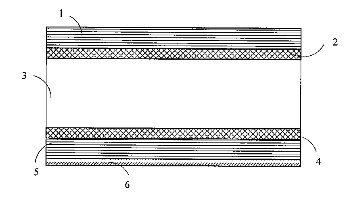
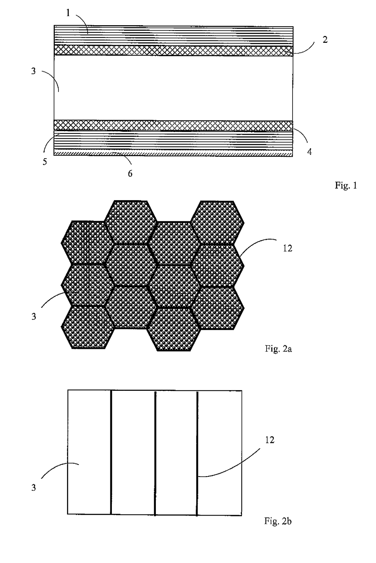
[0056]FIG. 1 shows a composite sandwich base panel comprising an upper surface layer 1, and lower surface layer 5, which sandwiches a composite foam core 3. Either side of the core is a barrier layer, 2 and 4. The entire panel is then surrounded by a plurality of external edge components (not shown). For the regions where the edge component will be attached to the panel, there may be a change in the local material composition of the composite core 3, and / or a change in the local geometry of the peripheral region. A wear layer 6 may be bonded to the lower surface layer 5.

[0057]Depending on the manufacturing process used, some embodiments of the invention include a cellular structure incorporated into the composite foam 3. FIG. 2A is a horizontal cross section of a hexagonal cellular structure, 12, that is incorporated into the composite foam core 3 and FIG. 2B is a vertical cross section of a hexagonal cellular structure, 12, that is incorporated into the composite foam core 3. Simil...


PUM

PropertyMeasurementUnit
Fractionaaaaaaaaaa
Fractionaaaaaaaaaa
Fractionaaaaaaaaaa

Abstract

The invention relates to a composite sandwich base panel for a Unit Load Device. The panel comprises an upper surface layer comprising fibre reinforcement material, a lower surface layer comprising fibre reinforcement material, and a central core section where at least the majority comprises a plurality of particles bound in a matrix material. The upper surface layer and lower surface layer are provided with a matrix material to bind them to the central core section.

Description

FIELD OF THE INVENTION[0001]The invention relates to a lightweight composite sandwich base panel, particularly for use as part of a Unit Load Device.BACKGROUND TO THE INVENTION[0002]Air cargo is typically transported in, or on, unit load devices that can either be in the form of containers or pallets. As with all aspects of the aviation industry, reducing weight is a key priority as it is synonymous with improved fuel efficiency and lower operating costs. The majority of unit load devices are currently made from high strength aluminium alloys, a legacy from the first designs of the 1960s. An aluminium alloy can offer a suitable combination of cost, density, and manufacturability. However it has two major drawbacks: its stiffness (and strength) to weight ratio and its susceptibility to plastic deformation.[0003]Composite materials, and in particular composite sandwich structures, are known to have high stiffness (and strength) to weight ratios.[0004]U.S. Pat. No. 3,556,448 (Dobbs) di...

Claims


Application Information

Patent Timeline
IPC IPC(8): B32B27/12B32B27/08B32B27/06B32B5/18B32B3/12B32B5/02B32B5/12B32B5/14B32B5/24B32B27/38B65D19/00B65D88/14
CPCB32B27/12B32B27/08B32B27/065B32B5/18B32B3/12B32B5/024B32B5/12B32B5/142B32B5/245B32B27/38B65D19/0004B65D88/14B32B2250/40B32B2260/023B32B2260/046B32B2260/025B32B2264/101B32B2264/102B32B2264/12B32B2266/057B32B2266/0271B32B2307/72B32B2605/18B32B5/02B32B5/14B32B5/28B32B7/04B32B27/04E04C2/205E04C2/243E04C2/365B32B2307/558B32B2307/536B32B2307/546B32B2307/552B32B2262/101B32B2262/106B32B2266/04B32B2250/03B32B2250/04B32B2250/05B32B2439/00B29C70/66B62D25/2054B65D19/0002B65D2519/00034B65D2519/00069B65D2519/00273B65D2519/00343B65D2519/00562B65D2519/00572B65D2519/00039B65D2519/00044B65D2519/00074B65D2519/00079B65D2519/00278B32B3/08B32B2377/00B32B2553/00B32B2266/08B32B2264/02B32B2305/08B32B2305/024B32B2305/022B32B2323/04B32B2307/71B32B2307/3065
Inventor FERGUSSON, ALEXANDER DOUGLASNEWMAN, ALEXANDER GEORGEMAYALL, ADAM PAUL LEONBALEV, TEODOR BOYKOVCASEY, JONATHAN PHILIPWANG, TONGDI GUISTO, MARC-ANTOINE LORMEL
Owner FERGUSSONS ADVANCED COMPOSITE TECH
Why Eureka
Try Eureka